#184197
First crack at it - may or may not change.


HD version:http://www.youtube.com/watch?v=8_tF2mRnk4Q&fmt=22

I'm not going for exact functionality, I'm making it how I want it. I'm not using trimpots to adjust speed, since I don't see myself adjusting them ever. just drinking beer :)

parts yet to arrive: switches, peltier unit (want pack to have space to hold two beers and keep it cold), other misc parts.

not done yet:
- voltage regulator (will have 8AA's powering it) need to limit it to 5v.
- AMP found here: http://jeremy.manlab.com/?p=47
- need resistors to adjust powercell voltage (just running one off power going to them)

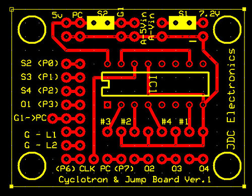
Parts used: 4 74HC595 shift registers and a 74HC4017B decade counter.
schematics are still being created.
code for arduino is here (working but still want to make some modifications for more flexibility) : http://jeremy.manlab.com/wp-content/upl ... Bv0.82.txt

Work in progress status is here: http://jeremy.manlab.com
Tyrael, wibbleBink liked this
#184204
Quick synopsis of how it's working:

Proton pack lights
Powercell (13 lights) (using 2 595 chips)
Cyclotron (using 4017B) - clock being taken from one of the lights on the powercell

Gun:
led bar graph (14 lights) (using 2 595 chips)
gun firing lights (using first and last pin on the 2 595 chips - see code)
flashing lights (pulling power from the led bar graph)
other lights (pulling 5v from when you power on. (will us a DPST switch to turn on power to the IC's (595/decade counter) and putting the pin to ground to start up the pack from the arduino
#187521
Don't know if you're looking for suggestions in your code, but if you ditch the delays and use time slicing instead, you'll get a much smoother transition between your sounds. It requires a lot more bookkeeping but the end result is nicer.
#189477
Man that breadboard gives me headaches to look at ;) (I much prefer perf-board)

Great job! This is basically my plan too (I just got a wave shield in the mail from Adafruit, need to solder it together).

One improvement I'd suggest is use PWM on the cyclotron lights.
#189861
Ah, I'm building with a Arduino Mega - so I have more PWM pins. Didn't realize that limitation.

You can fake it though, at least a little bit anyhow, using timings that are super short (microseconds basically) on any Digital IO pin. It's not a flexible as a pwm pin, but it's a way to do it...
#189872
It's not necessarily the pins... there are at least two (maybe three? I don't have the pinout in front of me) PWM-enabled pins available on the Duemilanove with the audio shield attached, but the three internal timers (two for PWM output and one for the main loop) used to generate the PWM signals are all tied up by the sound library so you're limited to pin 6 (which shares time with the main loop). Maybe the Mega also has more clocks available.

But yeah... so far I haven't needed more than the one PWM pin on my pack project, but I may try software PWM if the need arises...
#210237
I've started making a pack, then wasn't entirely happy so I started a second pack. I'll have two one fully functional and one with minimal lights, unless I decide to buy another arduino/wave shield.


First Original Pack
Image

Hybrid MDF/Foam Pack
Image

More pictures:
Image

Image

Image

Image

Image

Image

1st Pack - wasn't happy with the internals
Image
#210293
I've seen a lot of these builds where people are using the pink insulation foam. I really like the alternative and the outomce however was curious as to how one goes about painting a pack like this? I hope I'm not being retarded, but my first instinct would be to spray paint. In the end though, this would just melt the foam as far as I know, am I wrong or is there just another medthod entirely or a prep stage?
#210307
Looks like your website is down? Great work so far on the pack.

And I'm loving those lights (no sound on my laptop, so can't hear that). Every time I see all those wires, my brain just shuts down. Hopefully one day I can try and learn some of this electrical stuff and make some lights for myself.
#210376
I'm also going the Arduino/Wave Shield route, I'll be following your progress with interest.

Would you mind posting your code? The link on your website doesn't work, and being new to Arduino, I'd love to see how you've done things.

Also, the power cell generally has 15 lights. I've found that sitting LEDs on a prepunched board evenly hasn't worked so well. I'm gonna try hitting a few with a dremel tonight to shave off a bit of the bottom lip.
User avatar
By Crix
#210438
I'm not sure what it costs to etch a board, but www.batchpcb.com offers professionally done PCB etching on the cost of $2.50/square inch, with a $10 setup fee. From what I've read, the turnaround time is about a month, which isn't bad.

I'm considering doing it myself to make a holder for my bargraph LEDs and shift registers, I'd really like to stay away from the rats nest of wires that my breadboard is right now.
#270092
Halloween is fast approaching!!!

I've laid out the boards and will have to double check layout/fitment before I start etching them. Will have to sort out proper documentation as the boards aren't all matched up yet.

Image

Image

Image

Hoping to be done documentation and double checking by tomorrow evening.
#270094
I've only done a little etching myself, and that was years ago, so I have no idea how much of an issue this is, but I've heard that having right angles in traces can trap acid in the corners when etching which might lead to them being broken. You may want to consider rounding the corners off.
#271834
GhostGuy wrote:I've only done a little etching myself, and that was years ago, so I have no idea how much of an issue this is, but I've heard that having right angles in traces can trap acid in the corners when etching which might lead to them being broken. You may want to consider rounding the corners off.
etching went fine other than a little misalignment issue. Handles right angles perfectly

Image

Image

two boards etched. three more to go. saving the gun board (most difficult) to the end. I started with the easy ones :)
#273258
well pack is done. I made a 3 mistakes on my electronics but they were minor ( that's what you get for rushing I guess). I laughed all through out the project because to me this is ridiculous. it's done and I'm sad and happy all at once.
Here it is.
http://www.youtube.com/watch?v=pUGTEm1lVNo

it will probably only see a few Halloweens then collect dust or stripped for parts. I can't be a Ghostbuster EVERY Halloween :)
#273382
Martinus wrote:Congrats, a really well executed project.

If you get the time I'd really love to see some circuit schematics.
due to time constraints I didn't create a schematic before creating the board. I might redo the electronics (and take my time) just for fun. that's what this whole project was really about.
#273988
haven't learned Eagle yet. Did it in express PCB.
I can post PDF/original PDE files but I would only use this as a reference. I would already change a few things and do it differently. I just wanted to get this project done for Halloween.

let me know.
#275266
I've implemented a similar circuit to yours. Don't have gun lights and my cyclotron uses a 555 for timing so I pulled the relevant bits out of your code:
Code: Select all
//Pin connected to SH_CP of 74HC595 (pin 11)
int clockPin = 6;
//Pin connected to ST_CP of 74HC595 (pin 12)
int latchPin = 8;
////Pin connected to DS of 74HC595 (pin 14)
int dataPin = 7;

// saved vals
byte dataPWRCL;
byte dataPWRCL2;

// data arrays
byte daPWRCL[15];
byte daPWRCL2[15];


void setup() {
  //set pins to output so you can control the shift register
  pinMode(latchPin, OUTPUT);
  pinMode(clockPin, OUTPUT);
  pinMode(dataPin, OUTPUT);
  
  daPWRCL[0] = 0x00; //00000000
  daPWRCL[1] = 0x00; //00000000
  daPWRCL[2] = 0x00; //00000000
  daPWRCL[3] = 0x00; //00000000
  daPWRCL[4] = 0x00; //00000000
  daPWRCL[5] = 0x00; //00000000
  daPWRCL[6] = 0x00; //00000000
  daPWRCL[7] = 0x80; //10000000
  daPWRCL[8] = 0xC0; //11000000
  daPWRCL[9] = 0xE0; //11100000
  daPWRCL[10] = 0xF0; //11110000
  daPWRCL[11] = 0xF8; //11111000
  daPWRCL[12] = 0xFC; //11111000
  daPWRCL[13] = 0xFE; //11111100
  daPWRCL[14] = 0xFF; //11111100
  
  daPWRCL2[0] = 0x80; //10000000
  daPWRCL2[1] = 0xC0; //11000000
  daPWRCL2[2] = 0xE0; //11100000
  daPWRCL2[3] = 0xF0; //11110000
  daPWRCL2[4] = 0xF8; //11111000
  daPWRCL2[5] = 0xFC; //11111100
  daPWRCL2[6] = 0xFE; //11111110
  daPWRCL2[7] = 0xFF; //11111111
  daPWRCL2[8] = 0xFF; //11111111
  daPWRCL2[9] = 0xFF; //11111111
  daPWRCL2[10] = 0xFF; //11111111
  daPWRCL2[11] = 0xFF; //11111111
  daPWRCL2[12] = 0xFF; //11111111
  daPWRCL2[13] = 0xFF; //11111111
  daPWRCL2[14] = 0xFF; //11111111

}

void loop() {
  for (int ii = 1; ii < 15; ii++) {
    
    //load the light sequence you want from array
    dataPWRCL = daPWRCL[ii];
    dataPWRCL2 = daPWRCL2[ii];
    // take the latchPin low so 
    // the LEDs don't change while you're sending in bits:
    digitalWrite(latchPin, LOW);
    // shift out the bits:
    shiftOut(dataPin, clockPin, MSBFIRST, dataPWRCL2);
    shiftOut(dataPin, clockPin, MSBFIRST, dataPWRCL);

    //take the latch pin high so the LEDs will light up:
    digitalWrite(latchPin, HIGH);
    // pause before next value:
    delay(50);
  }
}

I modified the pattern a little to remove the overlapping lights (two come on at at the same time). Have to sort out the audio stuff now but I don't have an amp so it's likely to be a bit redundant.

If it's not too much trouble could I have a copy of your finalised code?
Spengler/84 wand Gun Track

So...I had more than a little problem with dis[…]

Preview for #2 on DH's page. https://www.darkhors[…]

The_Y33TER , since the majority of the maker sc[…]

PKE Meter build project!

DO you have this files on sale?