#4816700
Ah what a shame :(

I was hoping you'd get this nailed in time. Still, look on the bright side, when you've finished you'll have a sweet pack to look at/play with every day :D
#4817925
Yeah, I realized a week or two before Halloween that I was spending all my time working on my costume and I was missing out on all the other fun Halloween stuff. It's better this way, now I have the whole year to perfect it!
Thanks Grimmy!
Grimmy GB liked this
By Lewis Tully
#4817979
This is awesome! Love seeing people take the time and effort to get it all right, and the work you are doing yourself is incredible! Unfortunately folks like me have to rely upon other people to do this kind of stuff, but you are doing it all yourself and it looks great! Will be watching this build closely! (I might have missed it, and if so, forgive me...) but are you going to mold your shell in fiberglass? Judging from what you've done so far I am guessing so. Again, excellent work!!!
User avatar
By Conqueror_Worm
#4818159
Thanks!
I wasn't planning on using fiberglass, but I guess I could give it shot. I've never worked with fiberglass before. I was thinking about vacuum forming the parts but I was worried that a thin plastic shell wouldn't be able to hold the weight of the metal parts.
#4823267
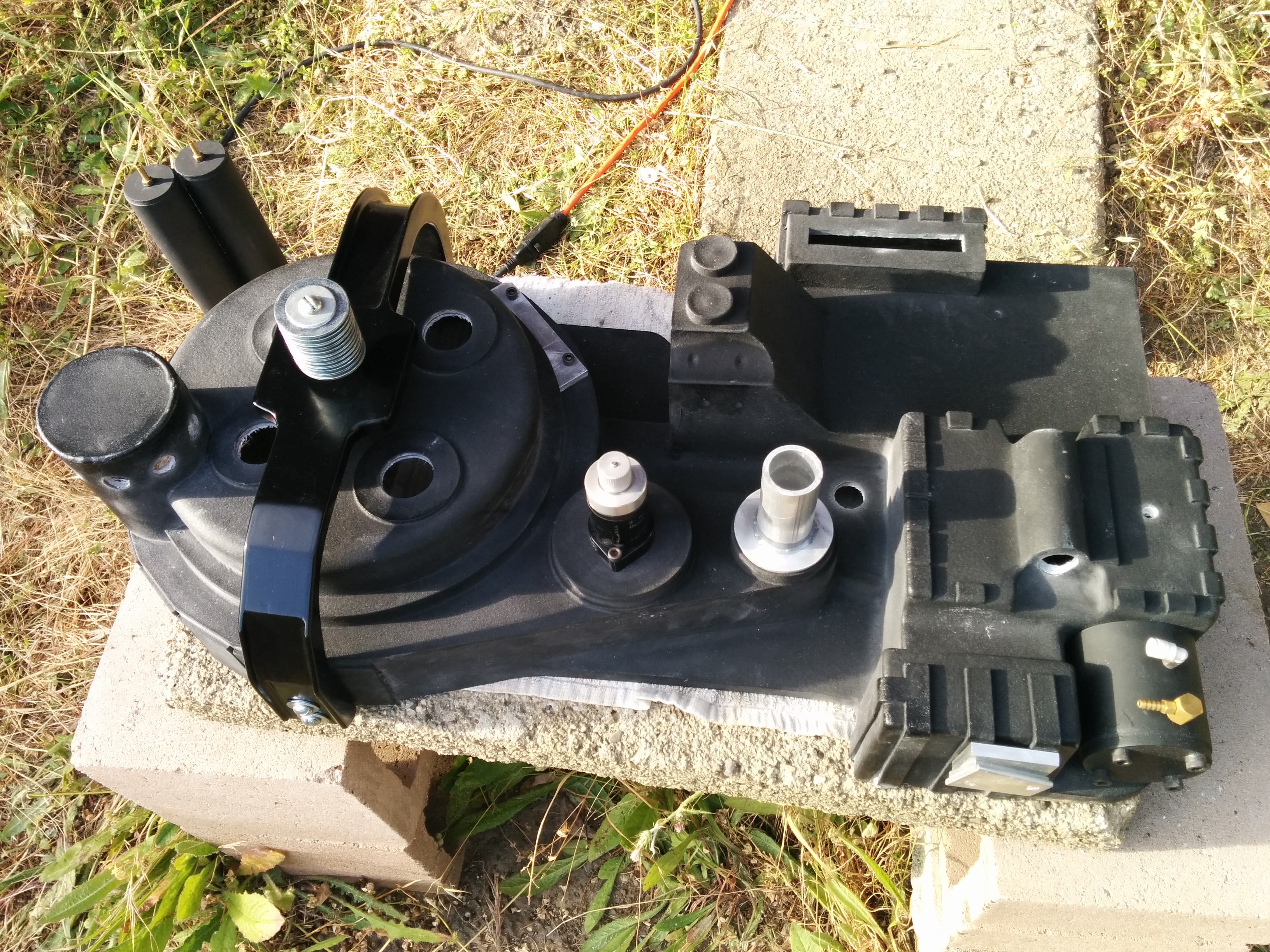
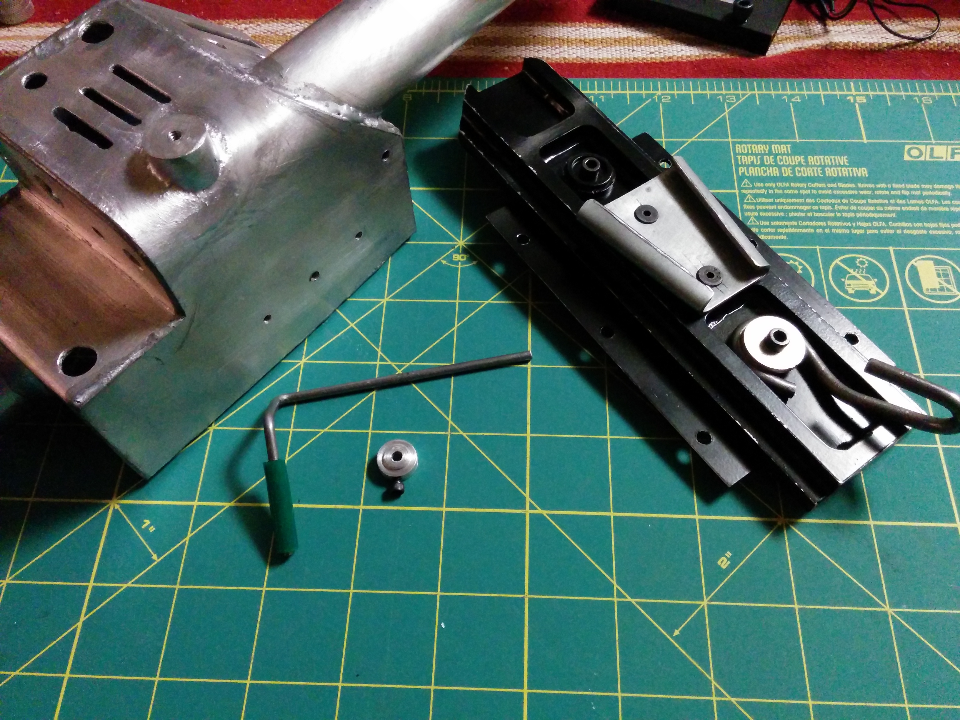
I was a little burned out on this project after October, but after a two month break, I have the proton pack bug again! While I was at my parent's house over the holidays, I took advantage of their better equipped shop to work on the ion arm cap and the banjo fittings.

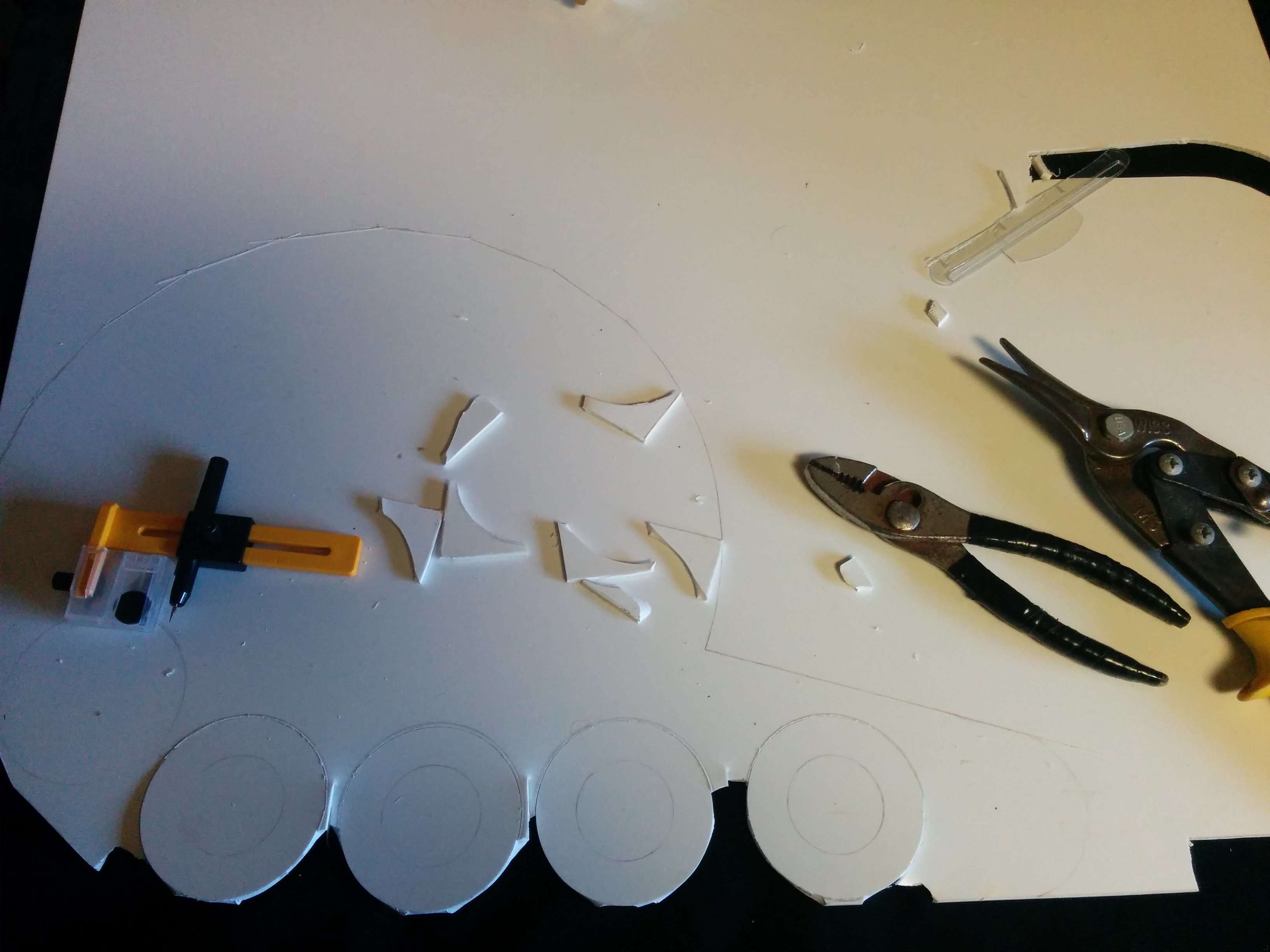
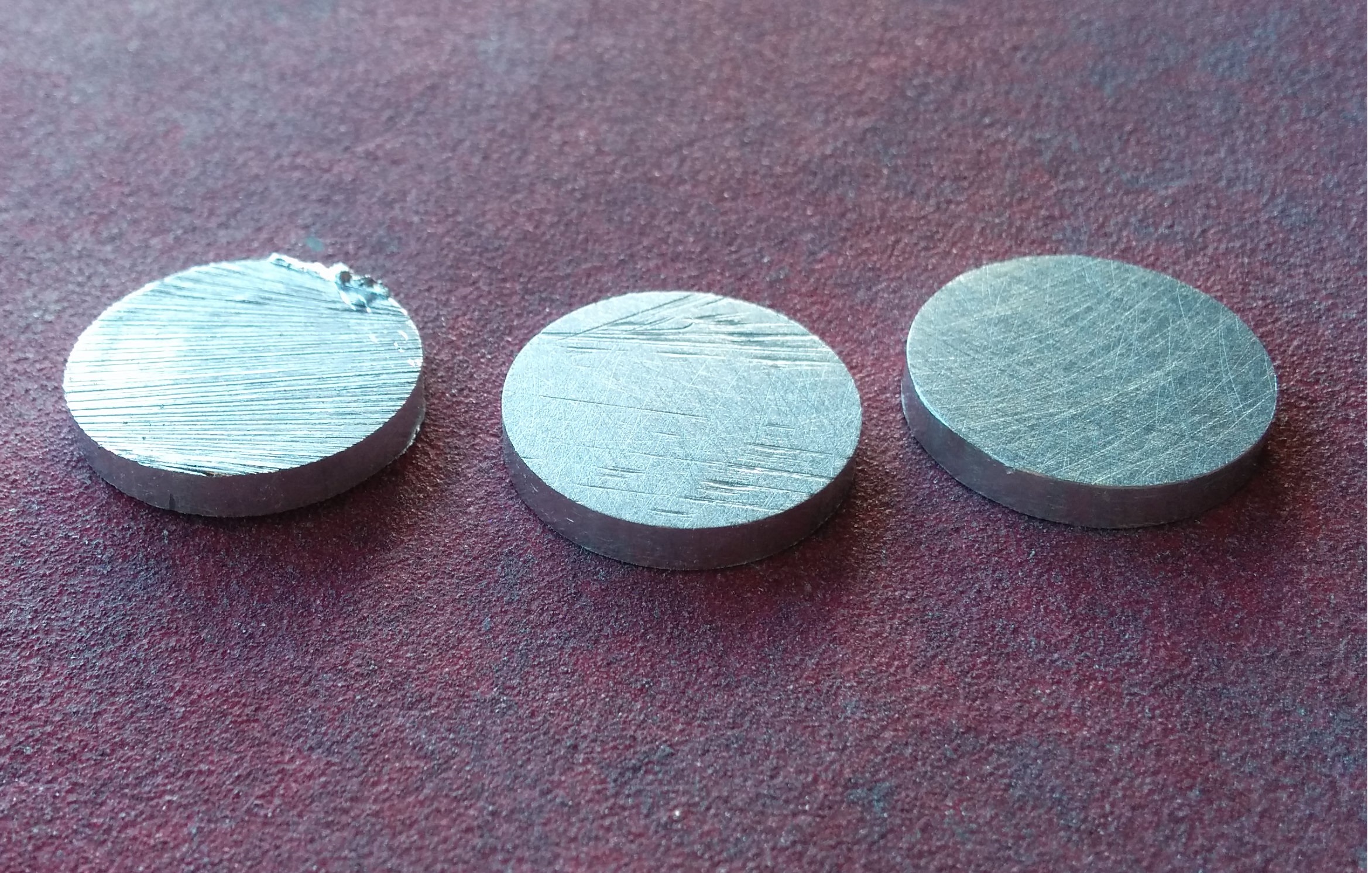
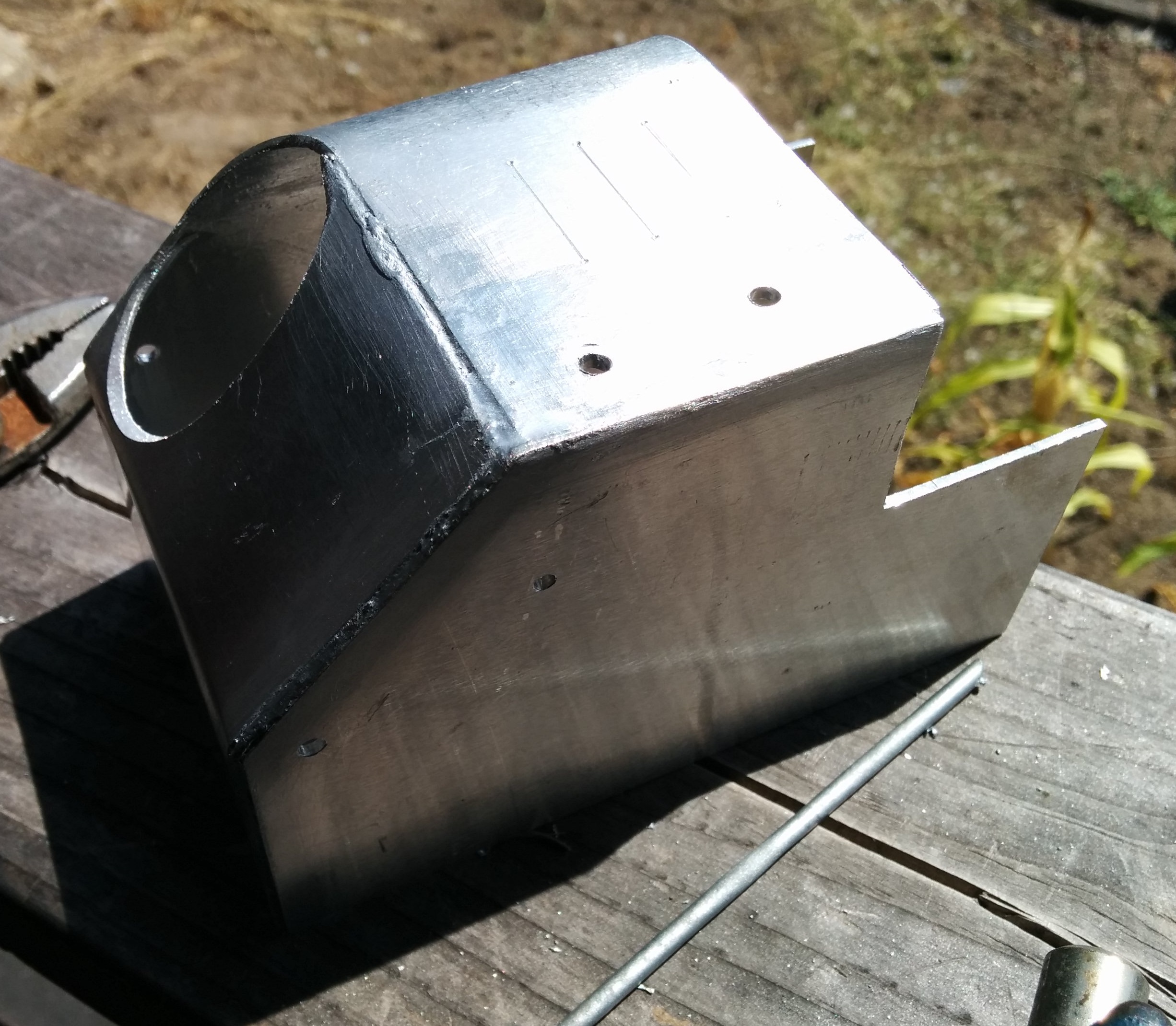
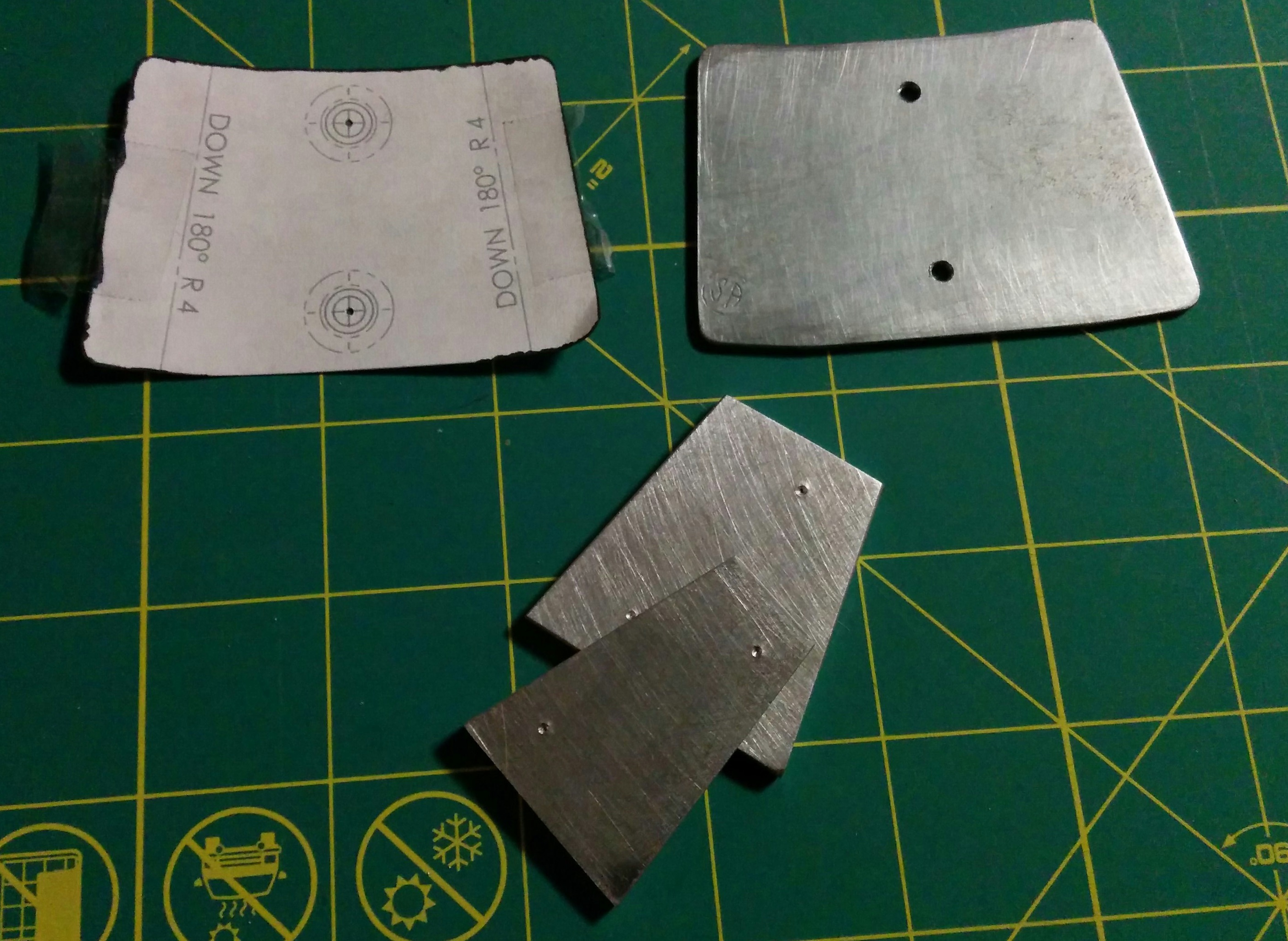
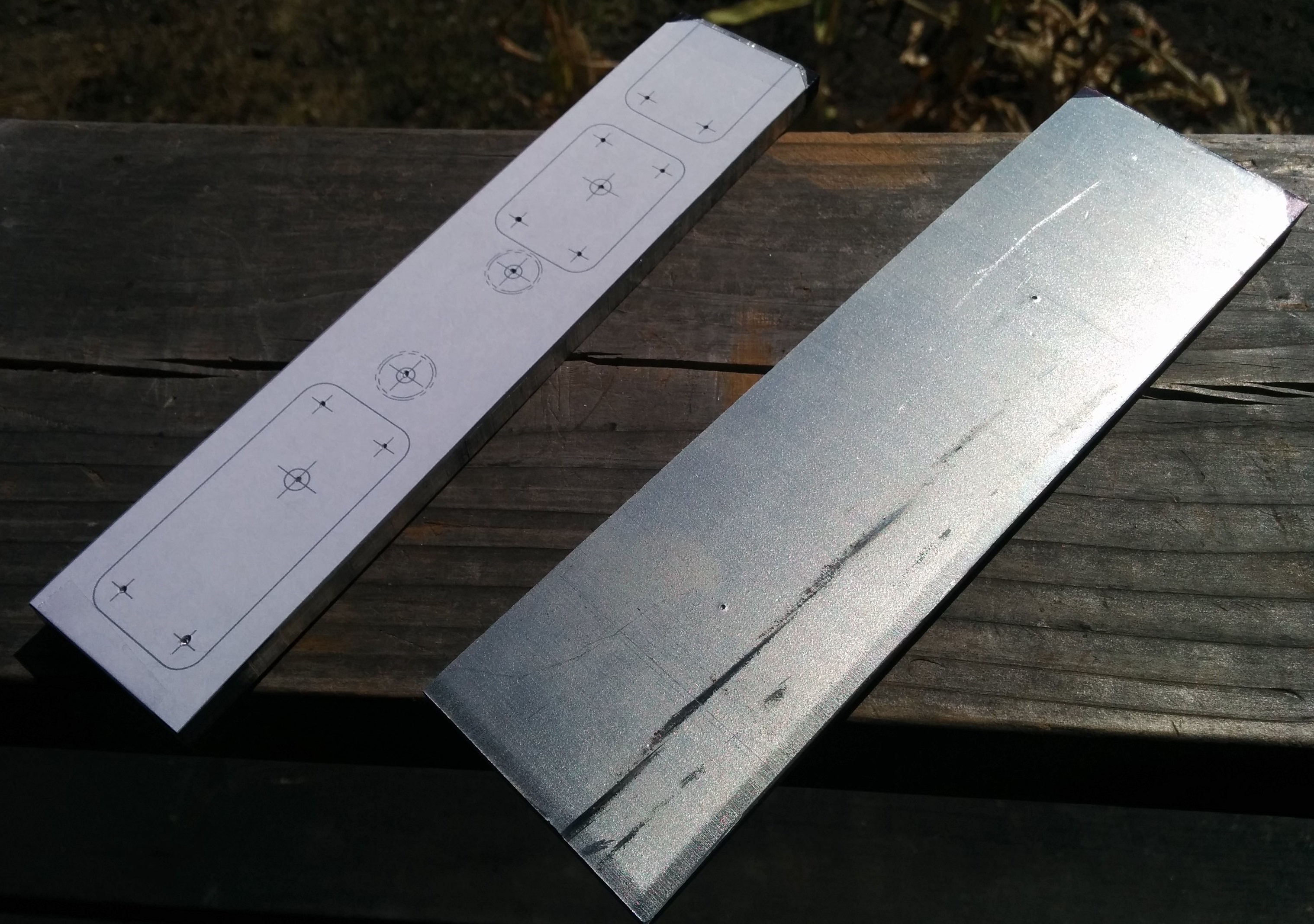
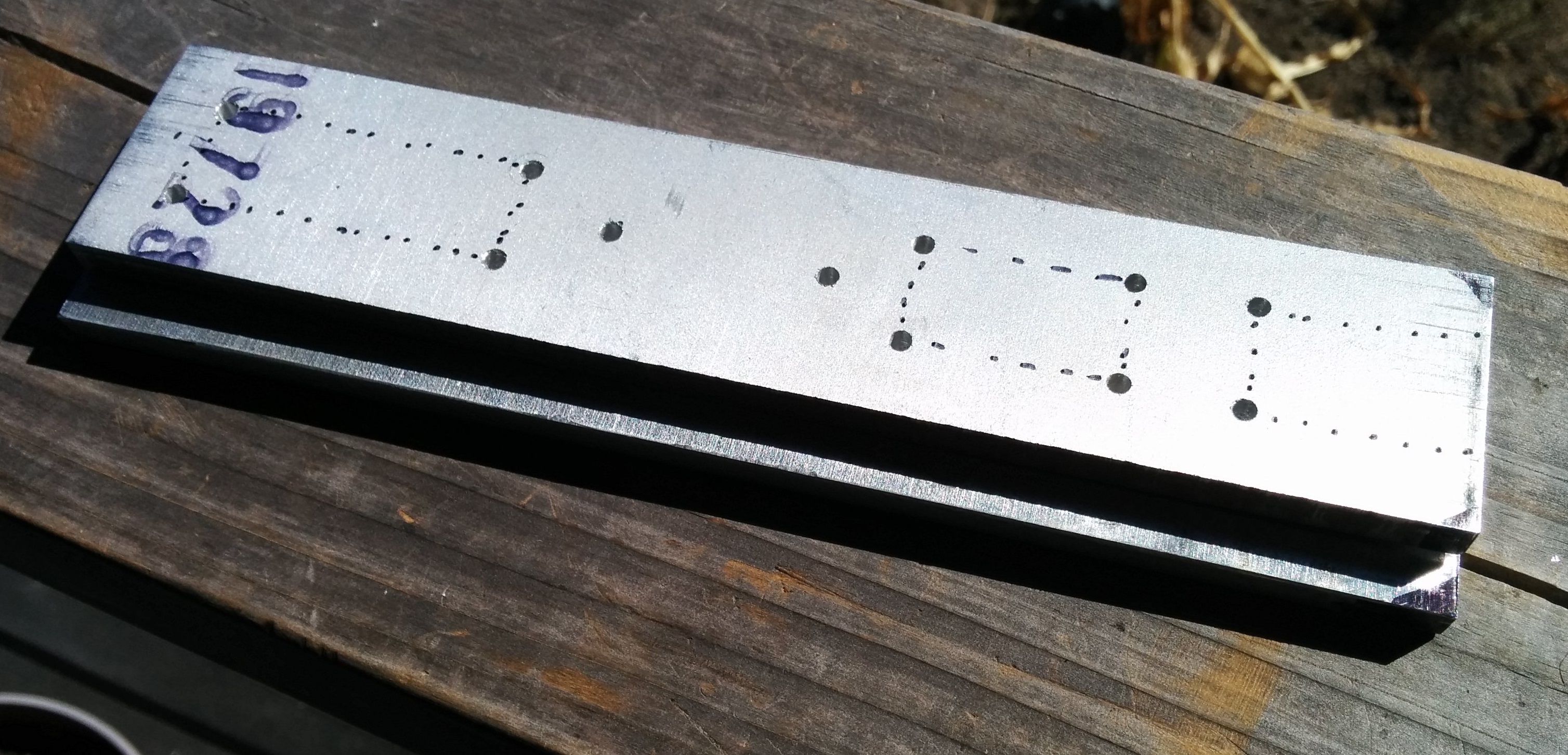
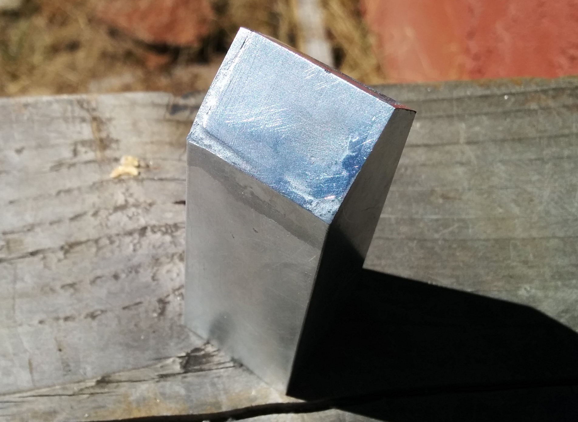
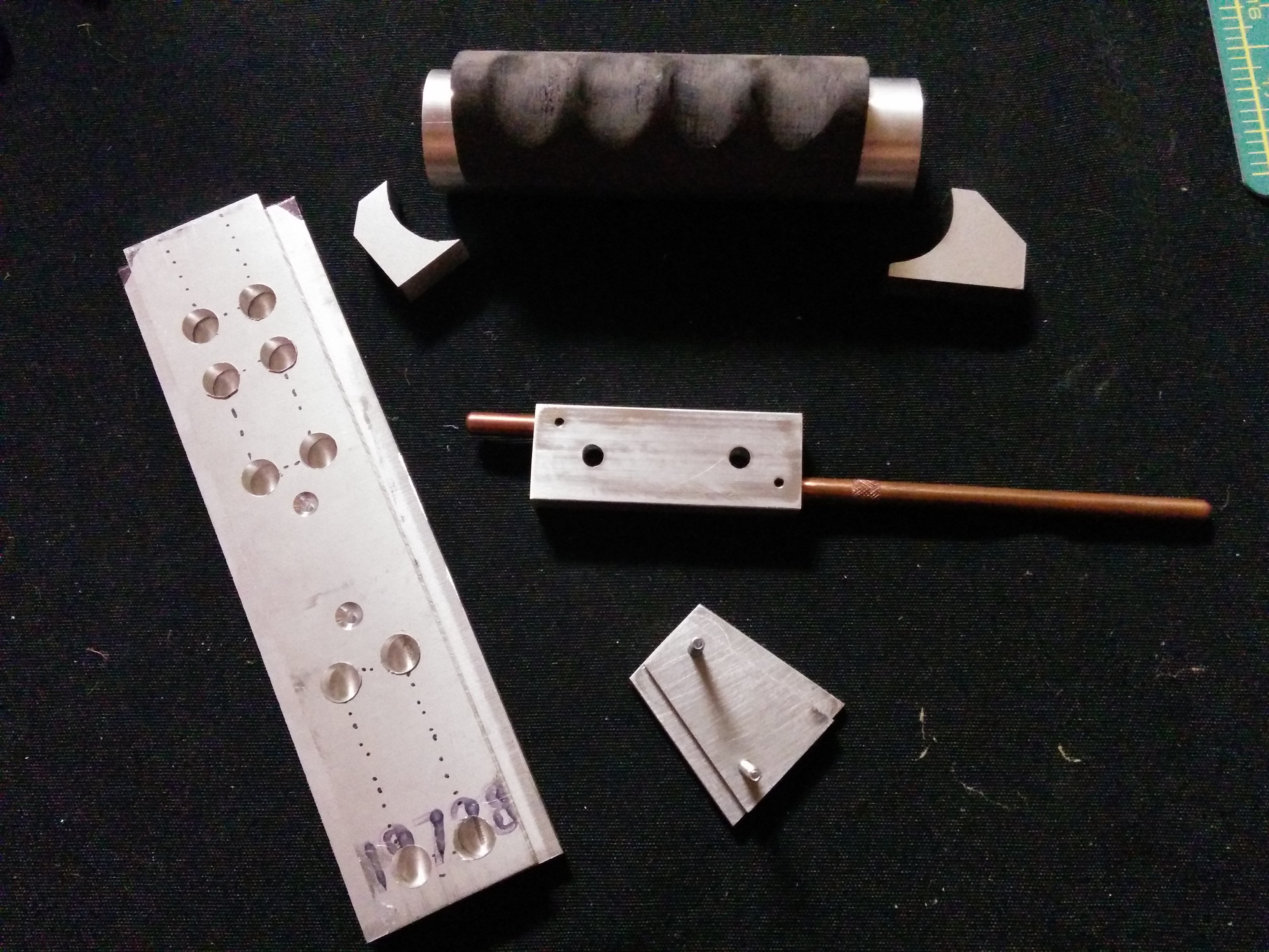
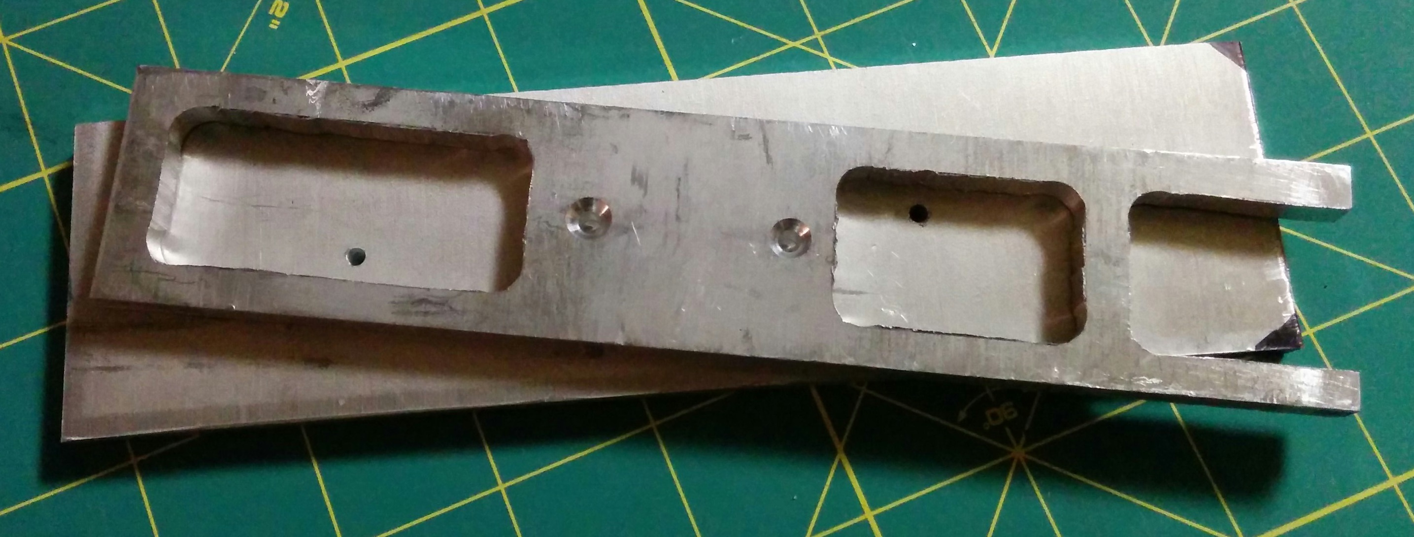
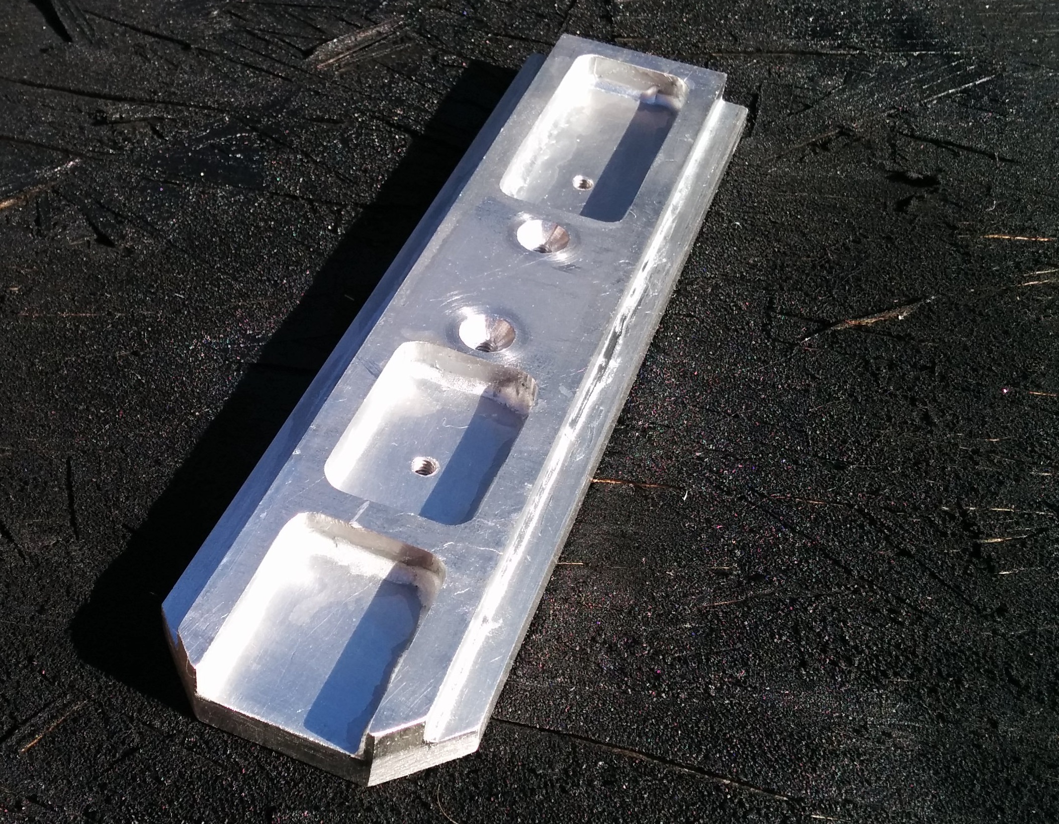
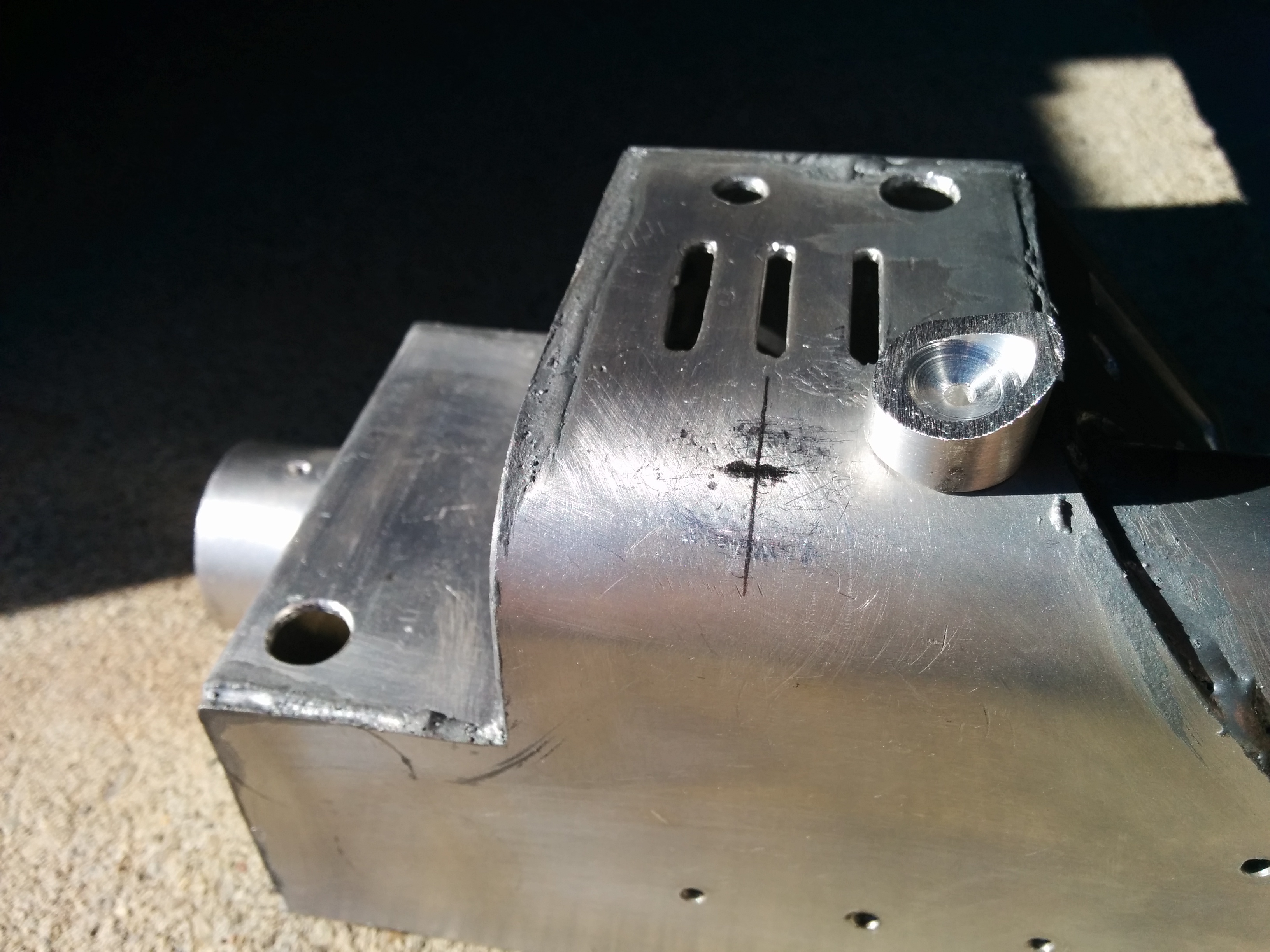
Starting with hunk of 
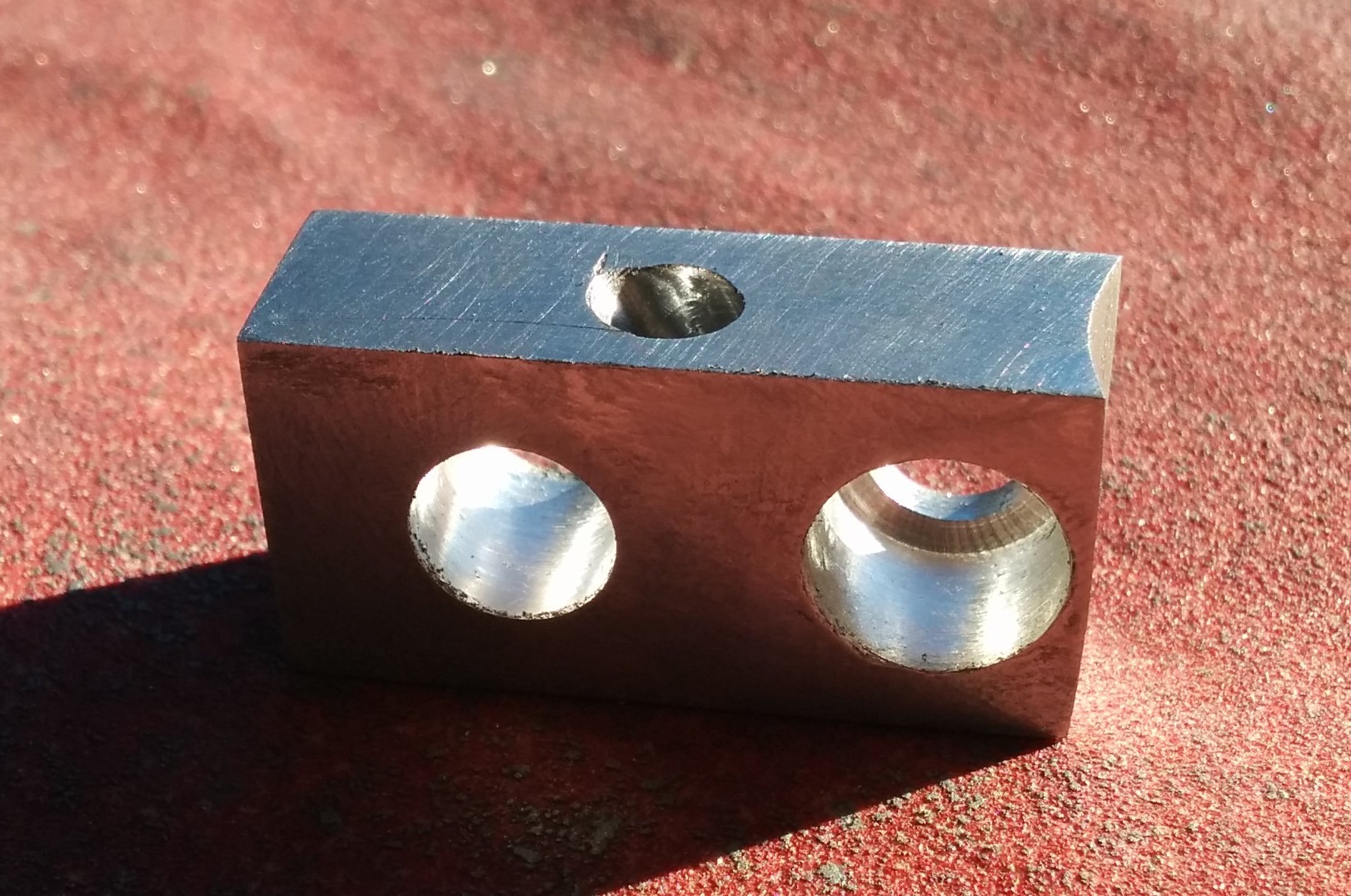
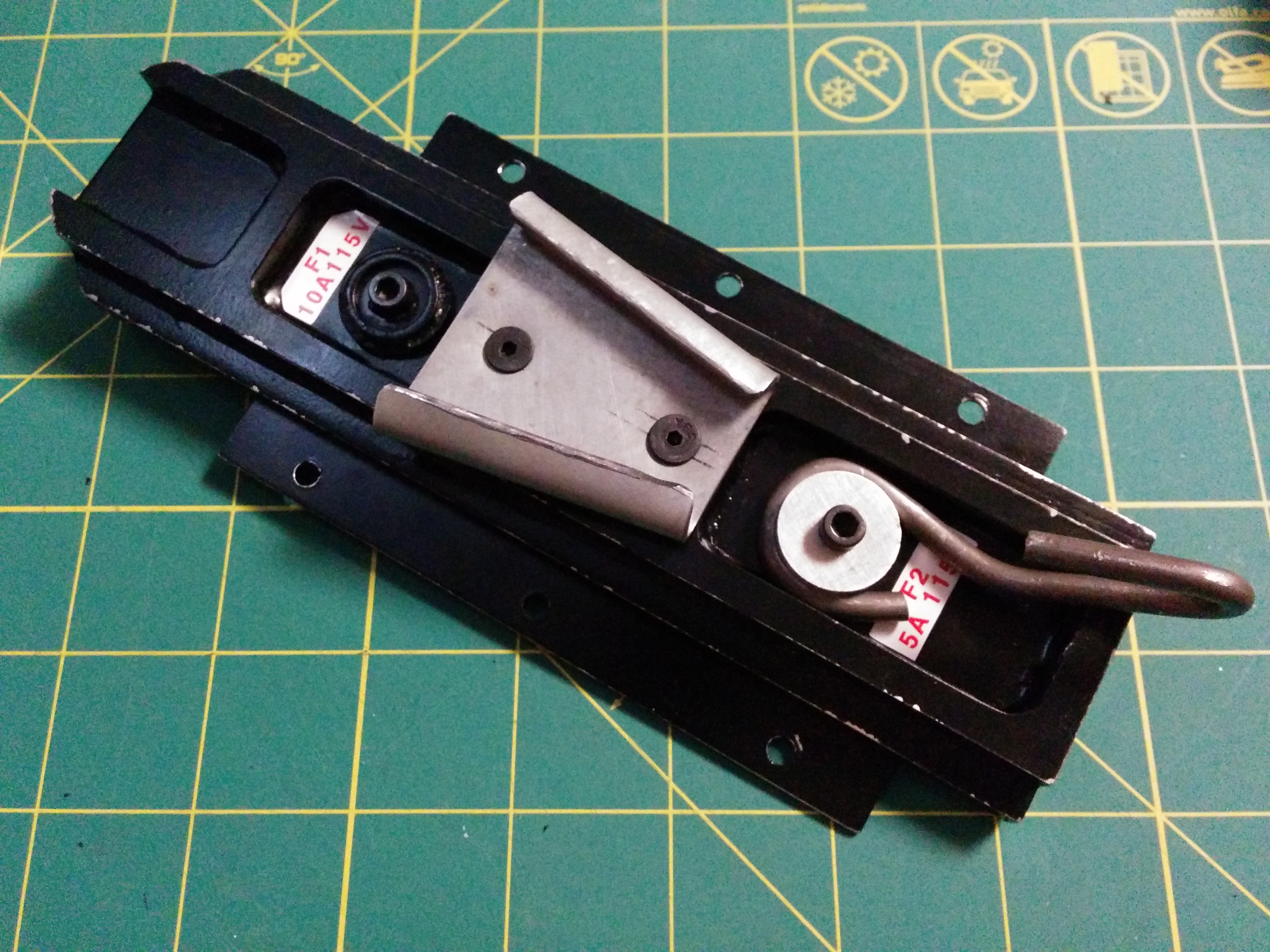
1" x 1/2" aluminum stock, I marked and center punched the location of the holes:
Image

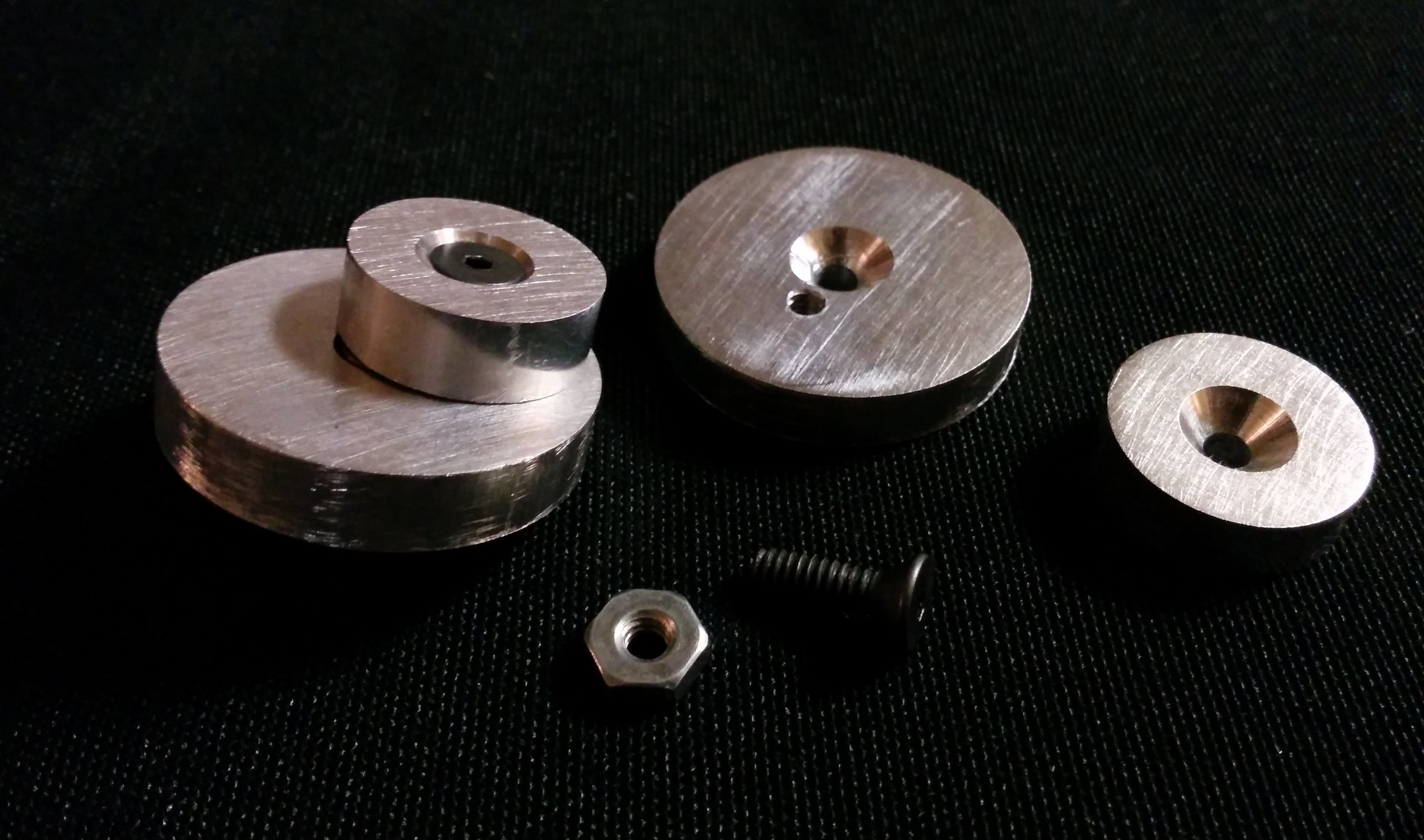
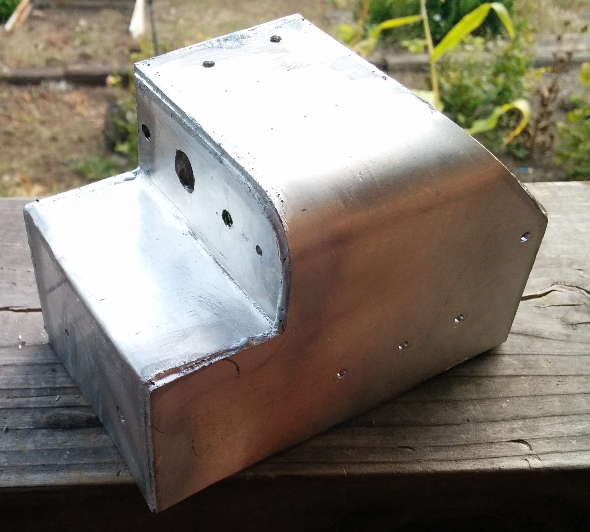
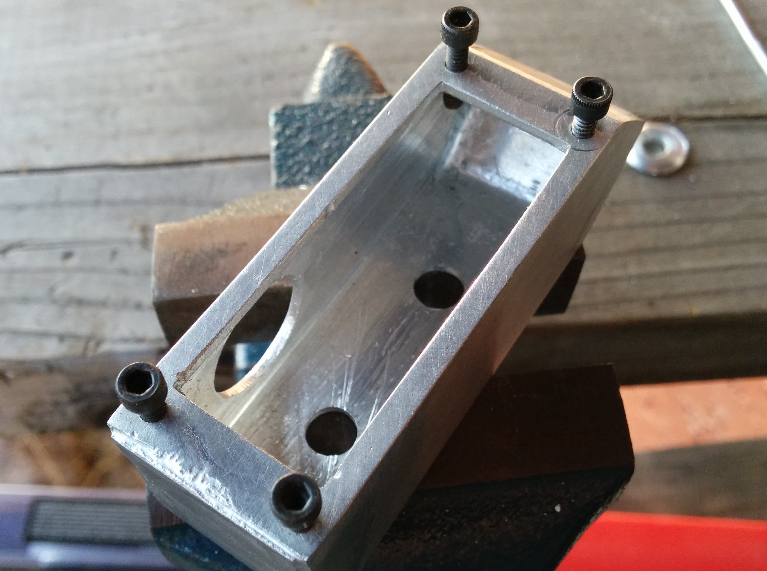
Then bored and counter bored the holes:
Image

Swarf can be sharp!
Image

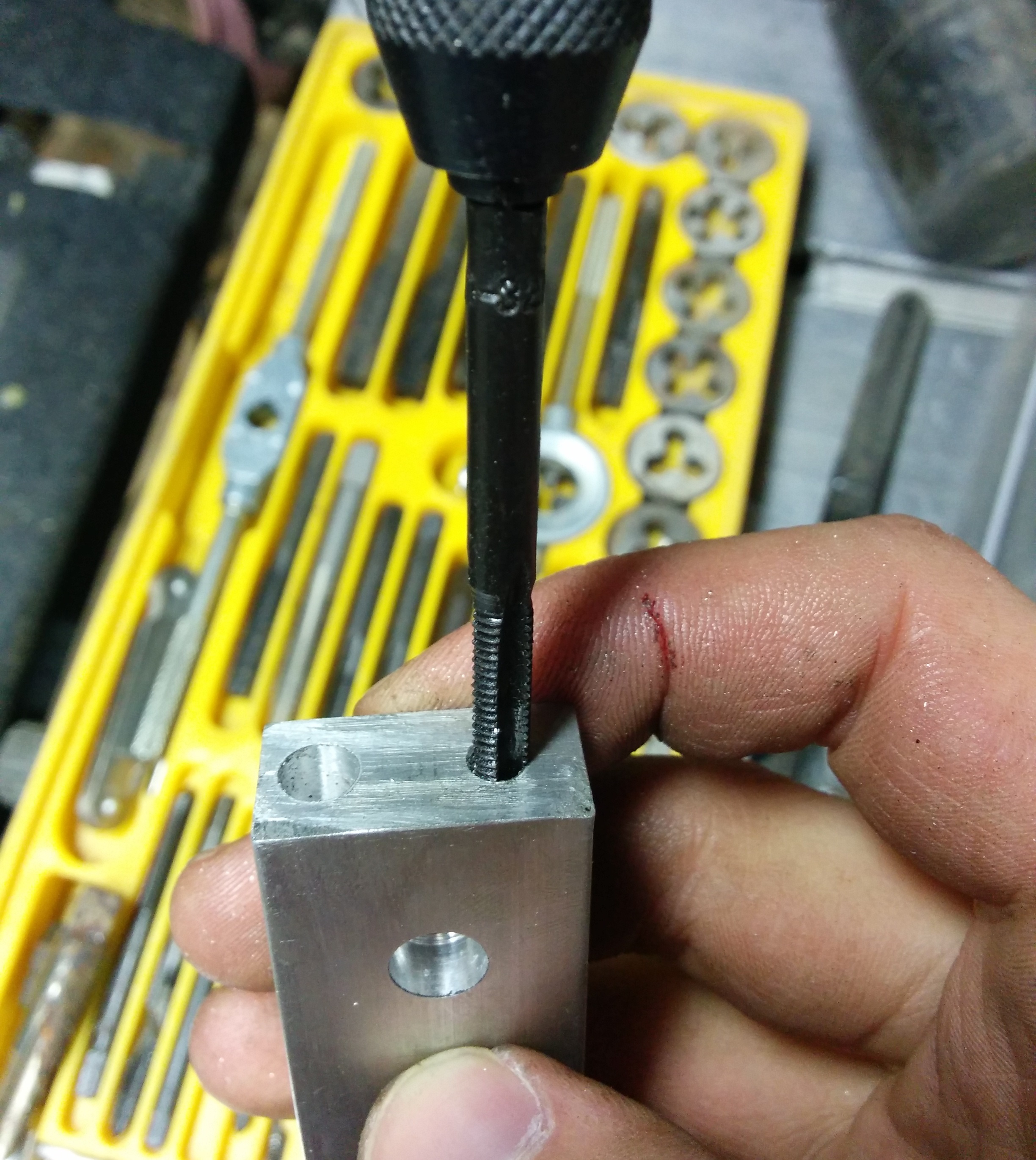
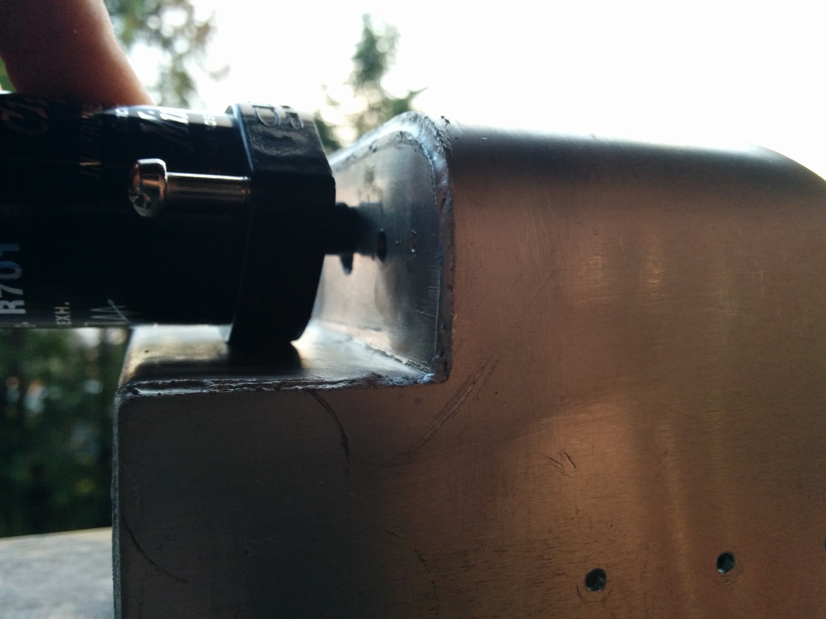
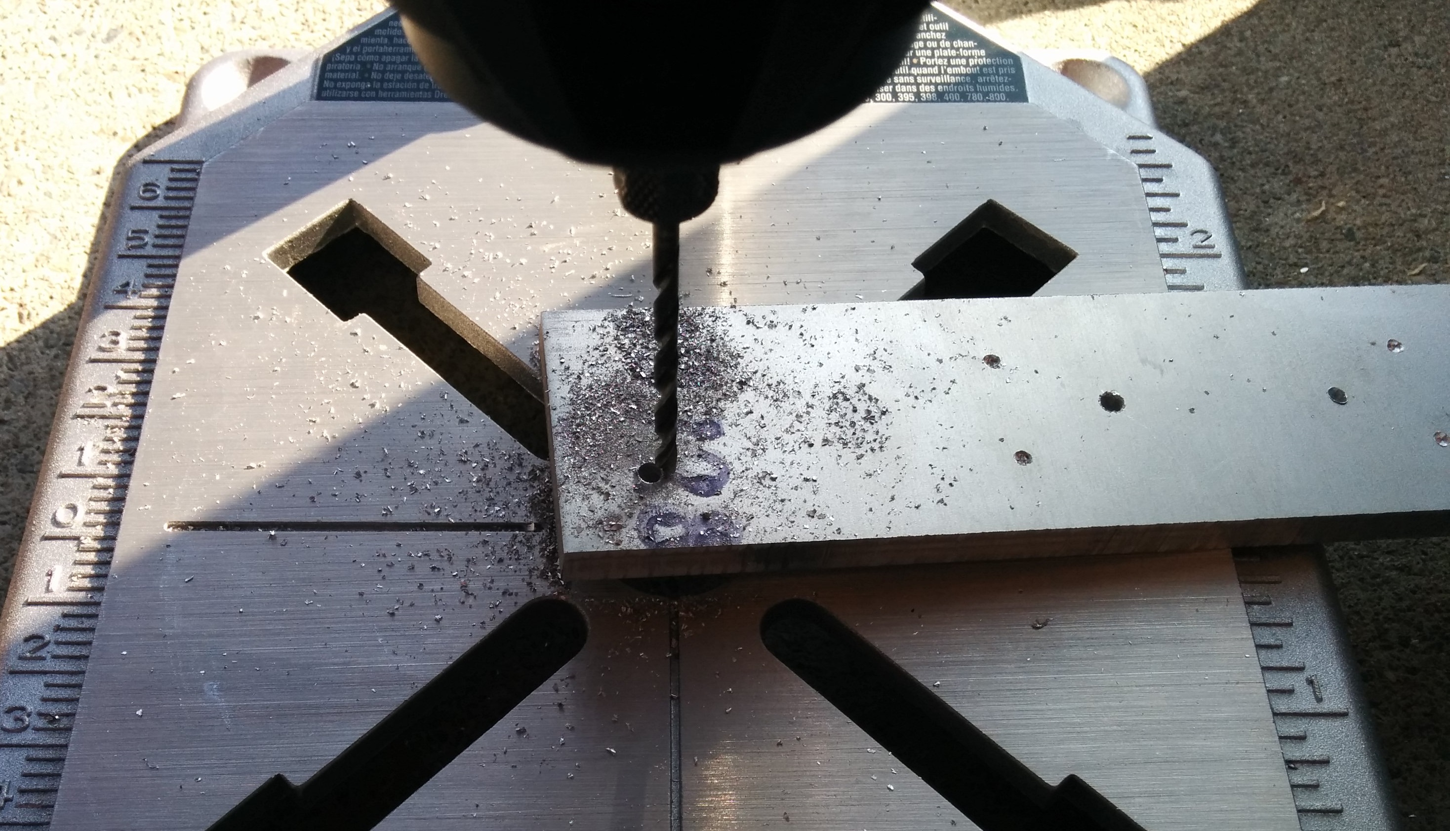
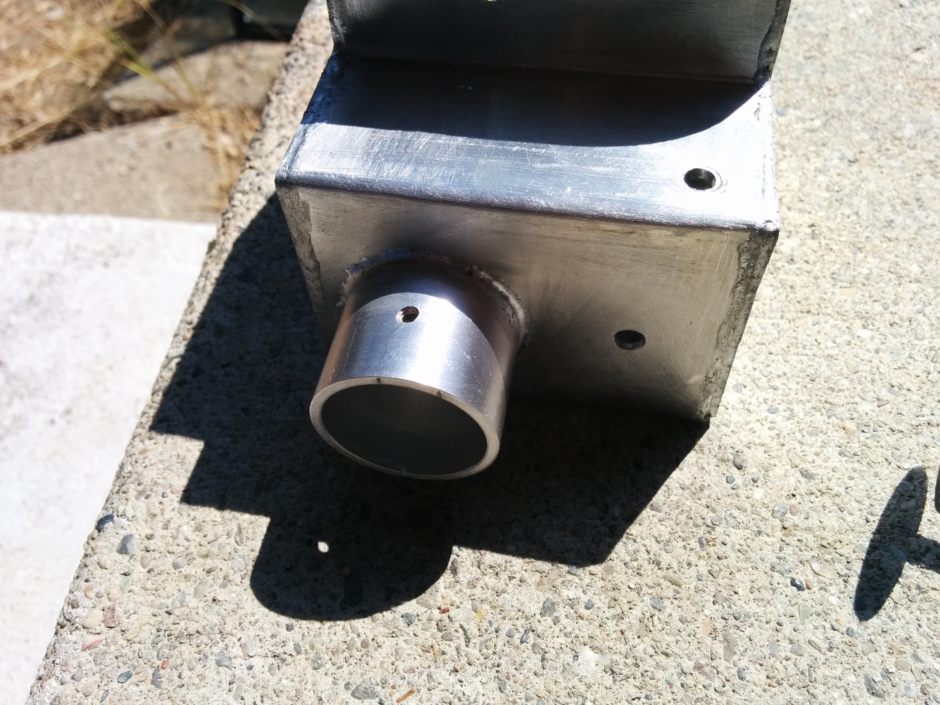
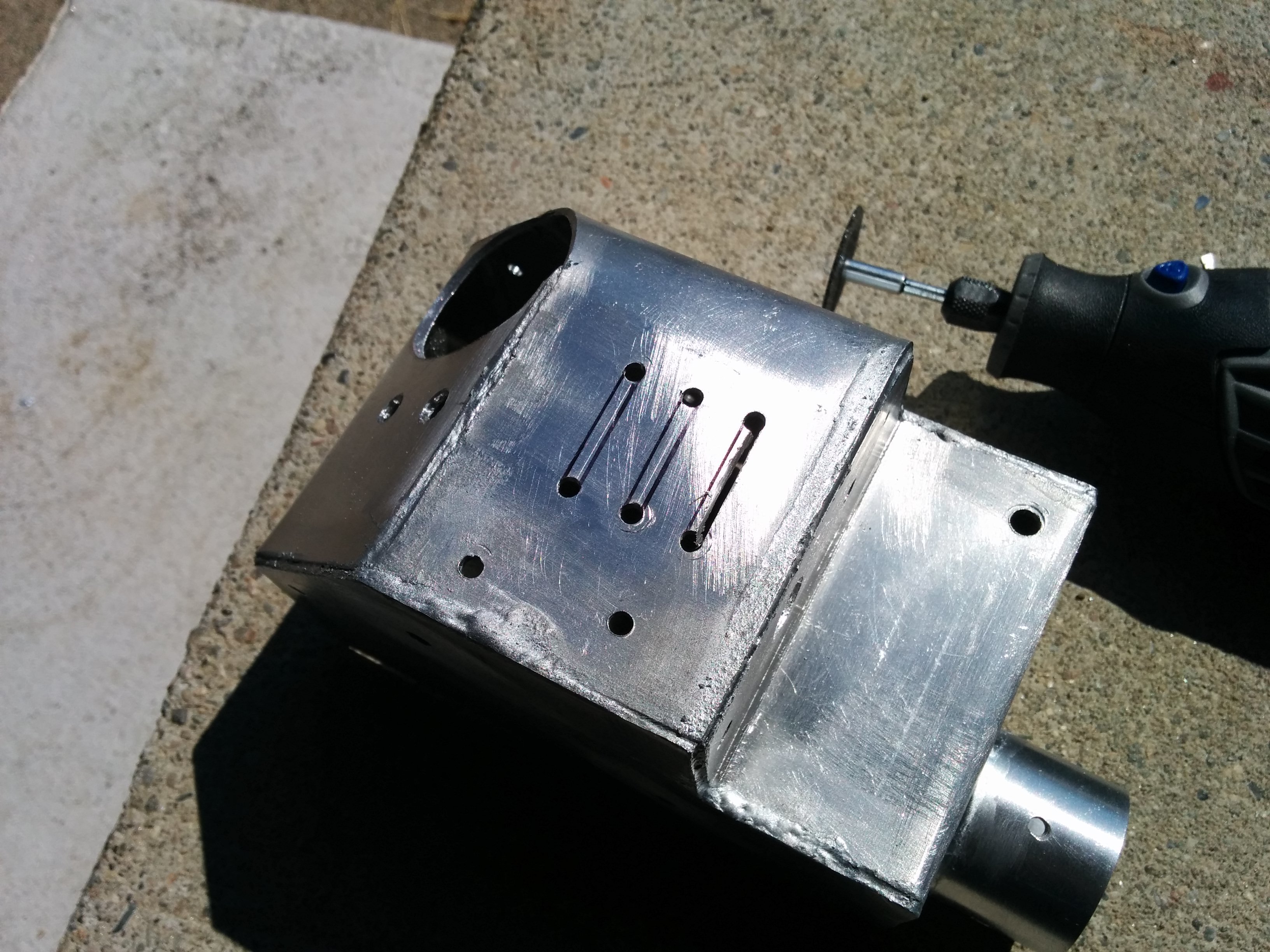
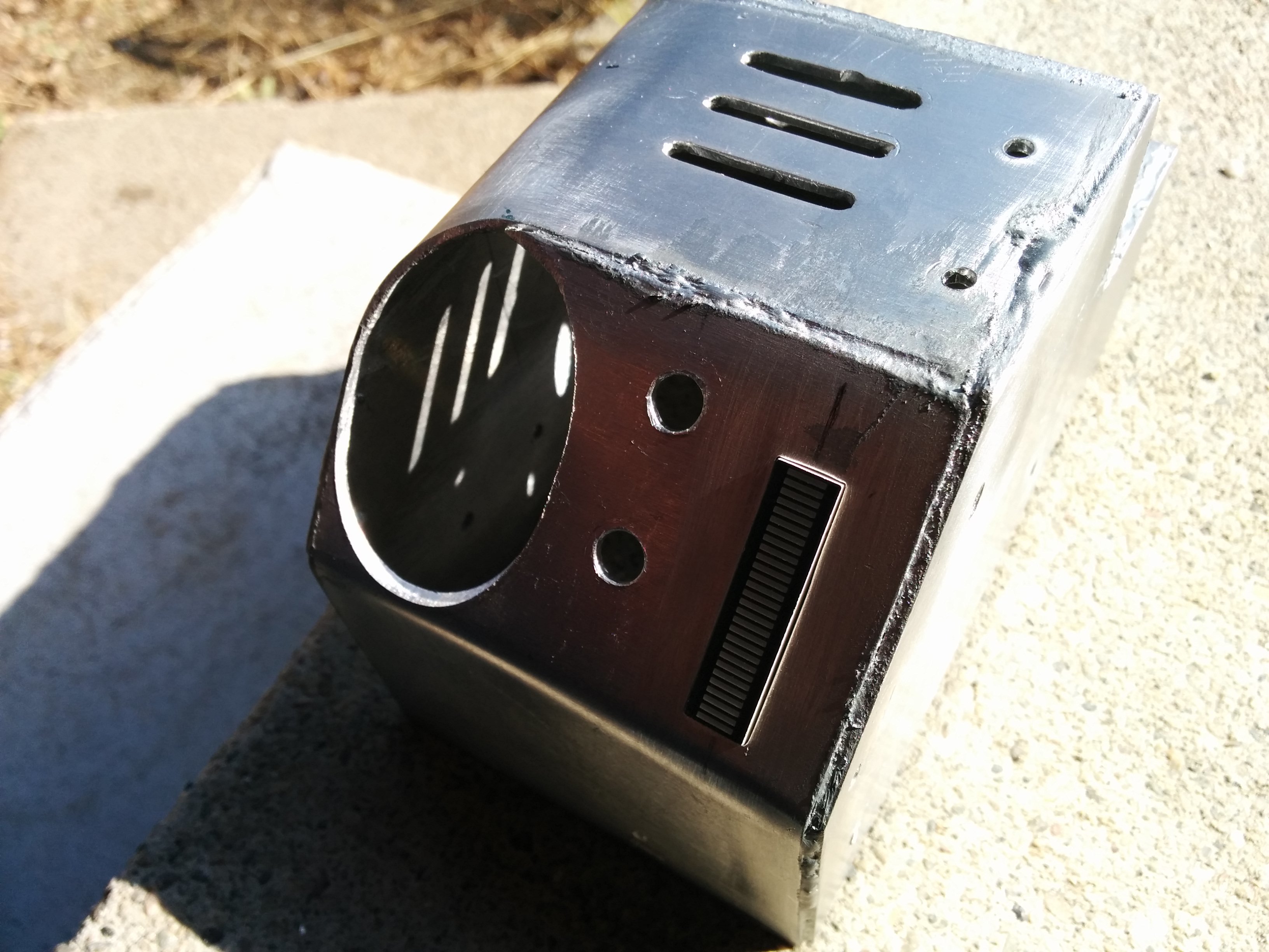
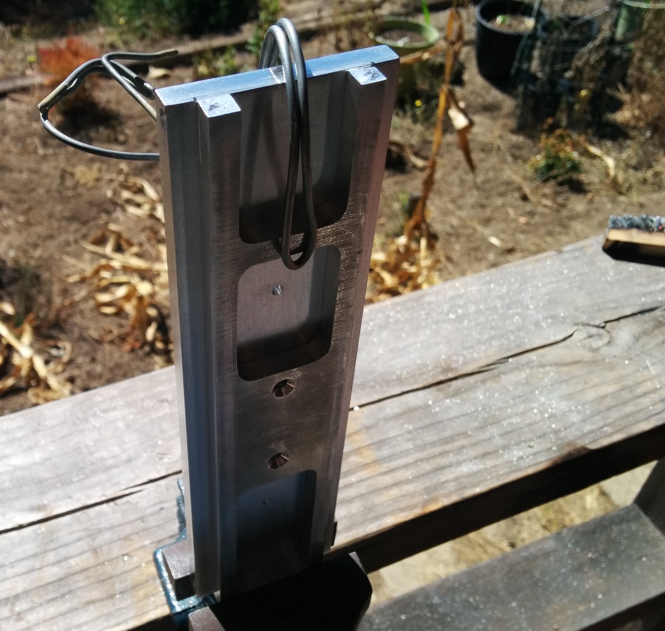
Drilling more holes:
Image

Tapping the hole for the 10-32 Clippard fitting:
Image

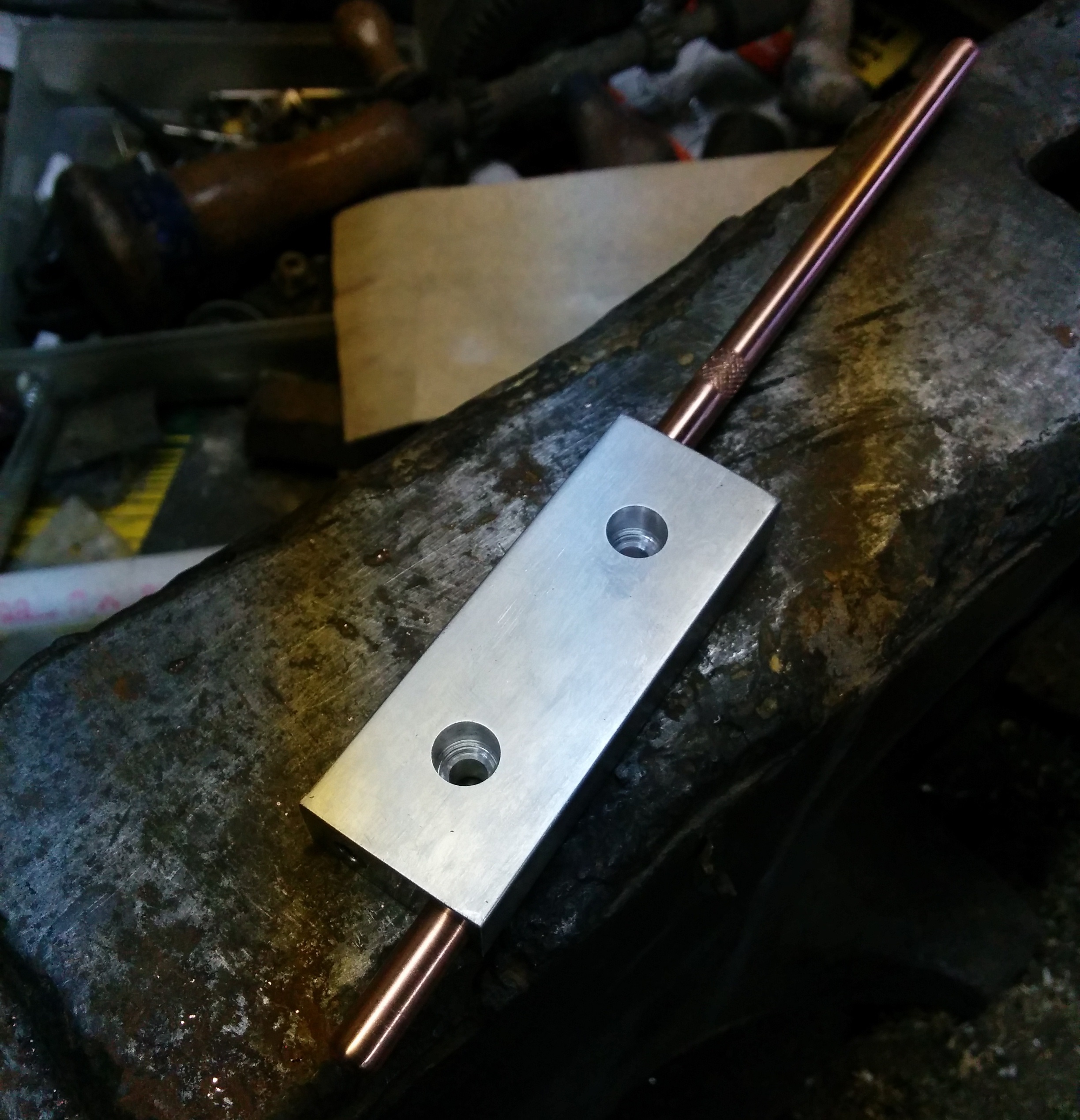
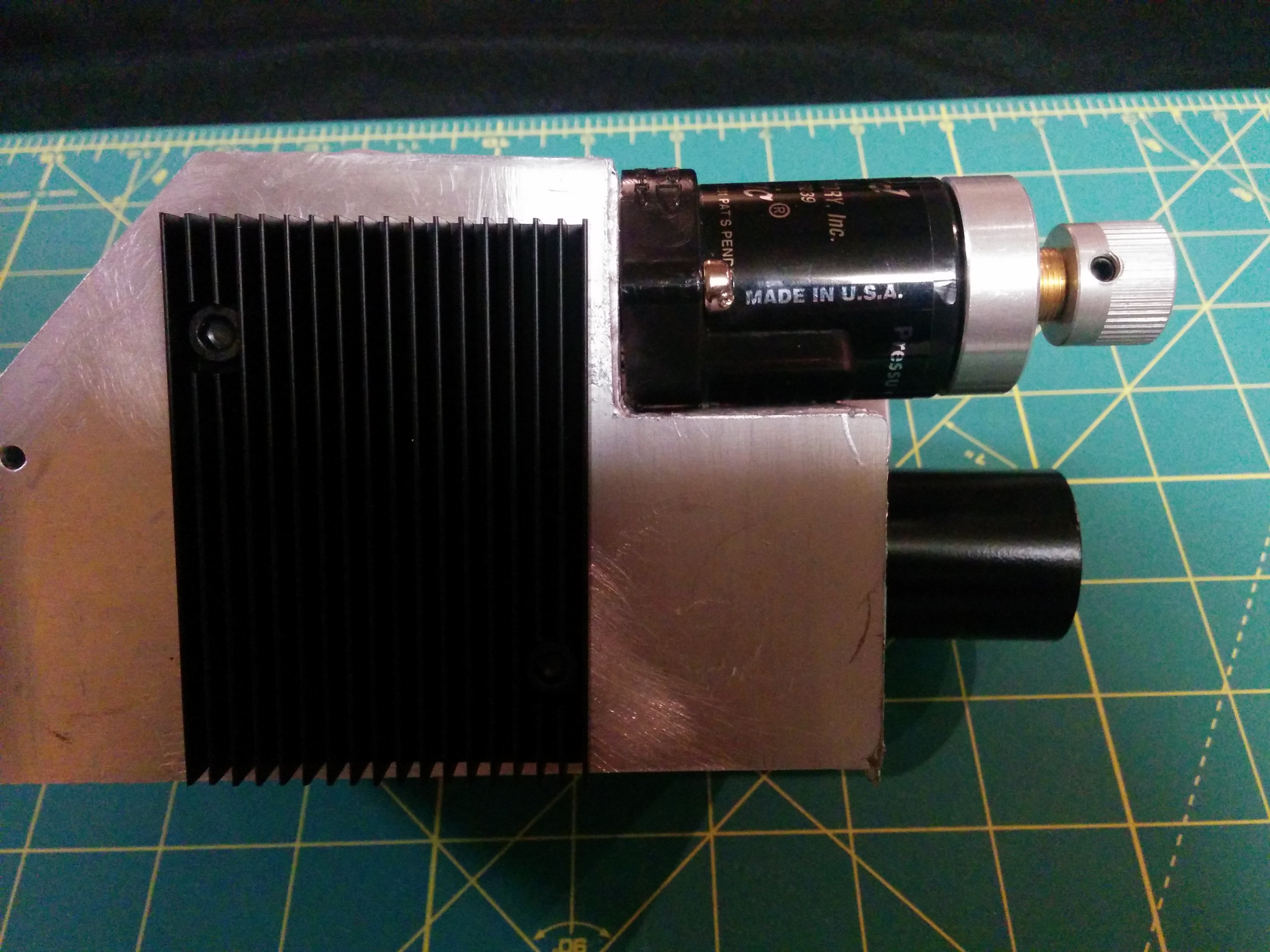
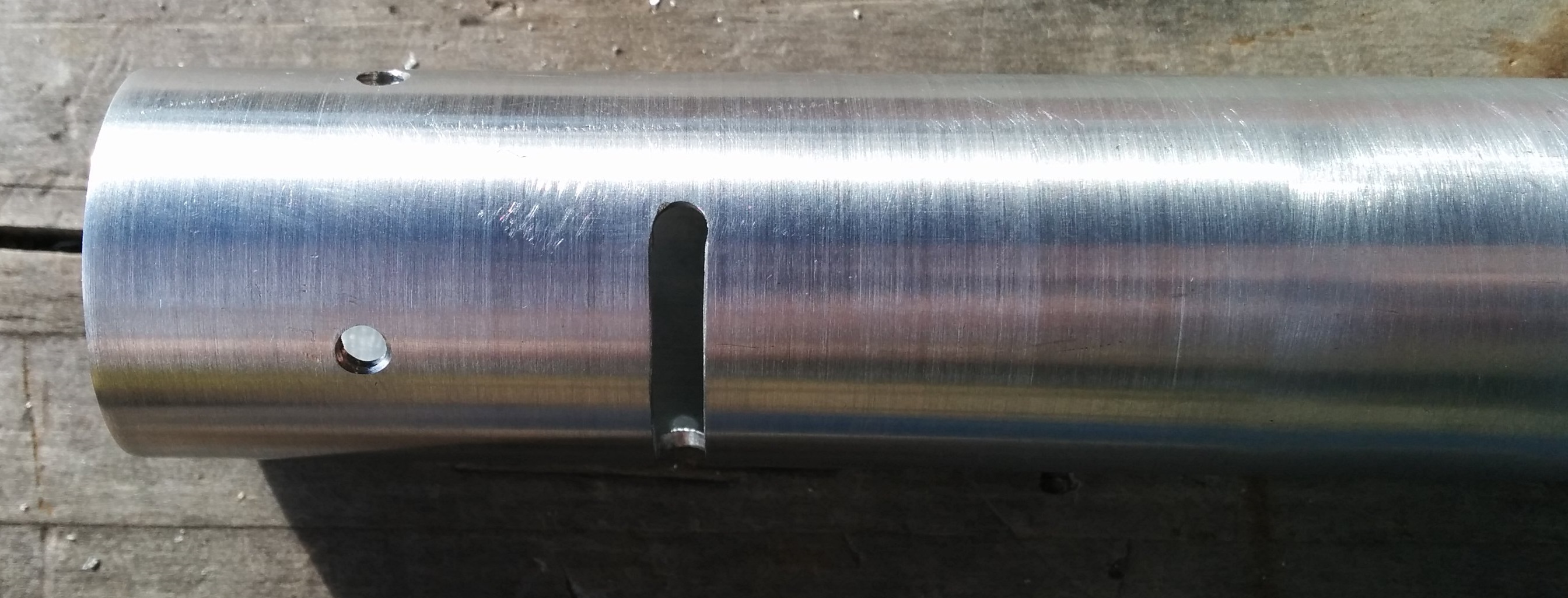
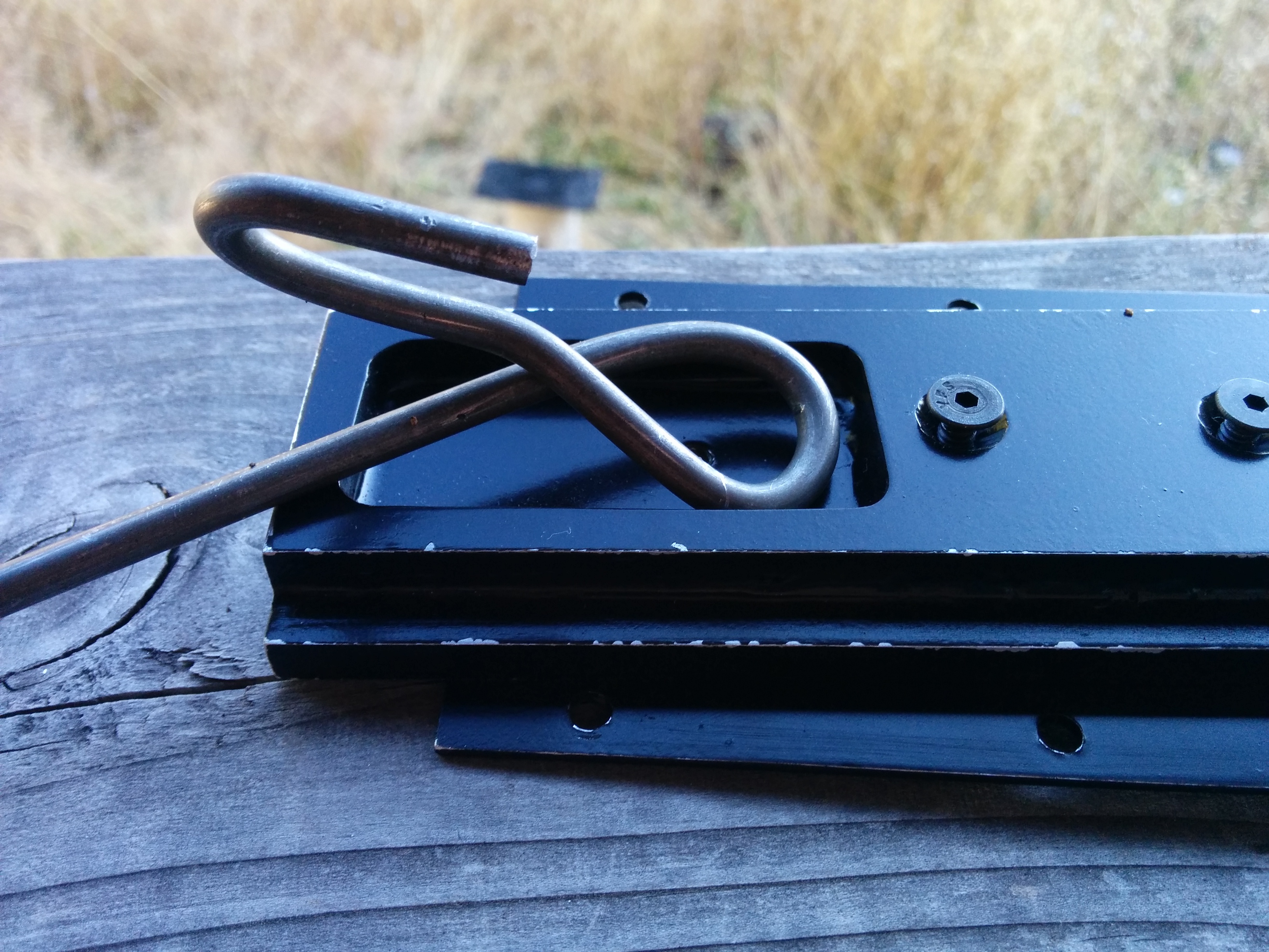
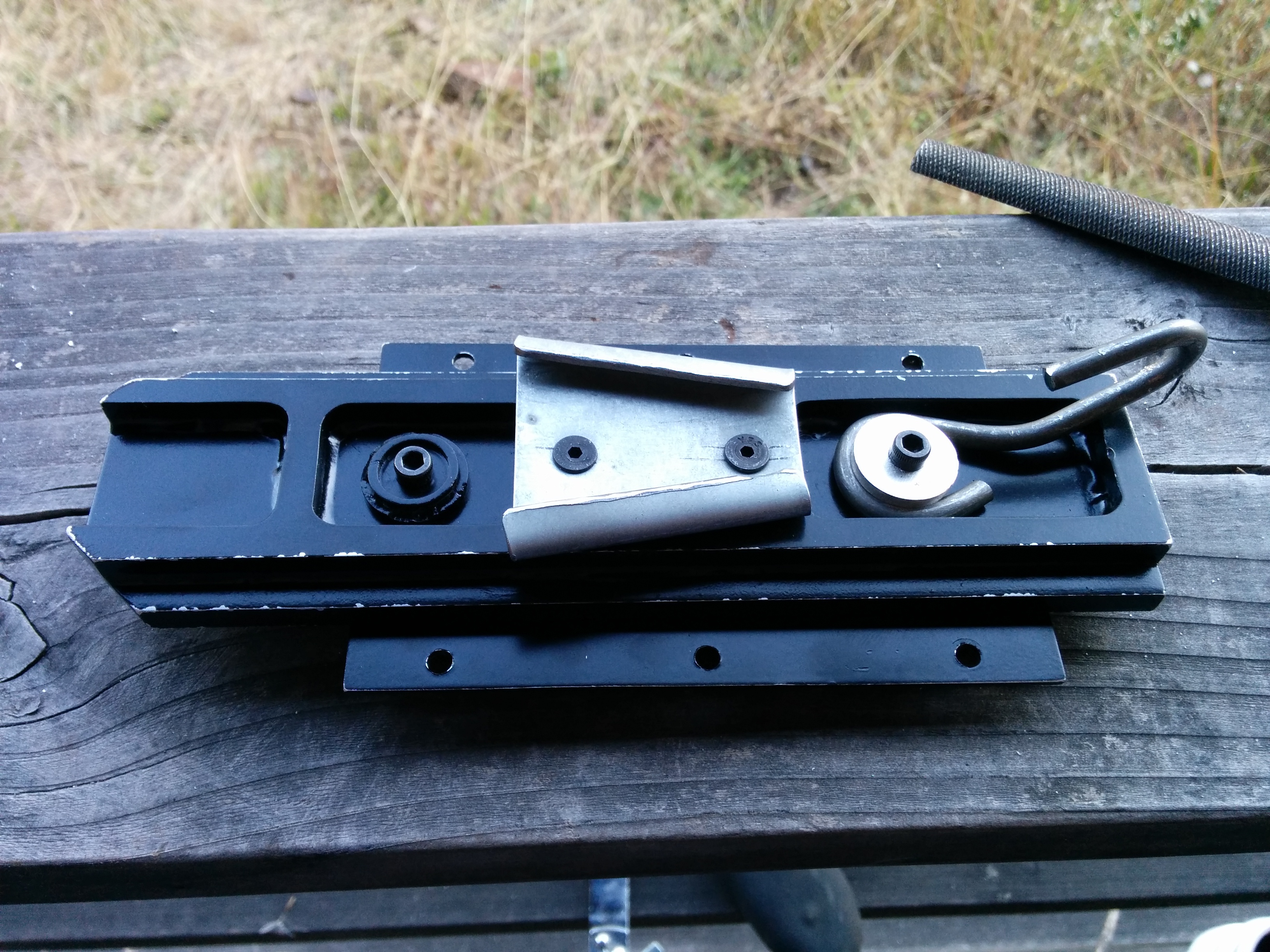
My cousin is a machinist and he was nice enough to knurl the copper rod for me:
Image

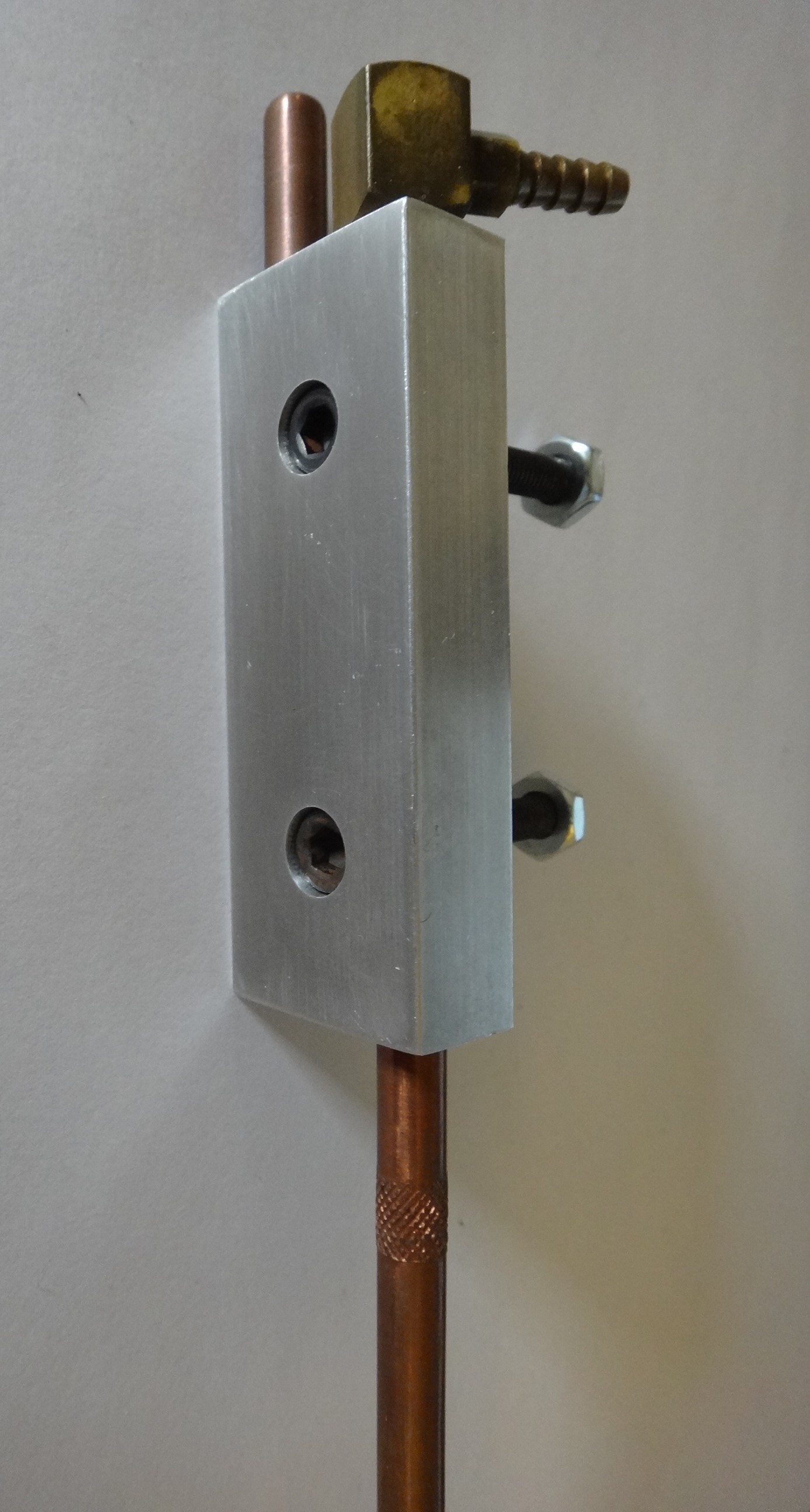
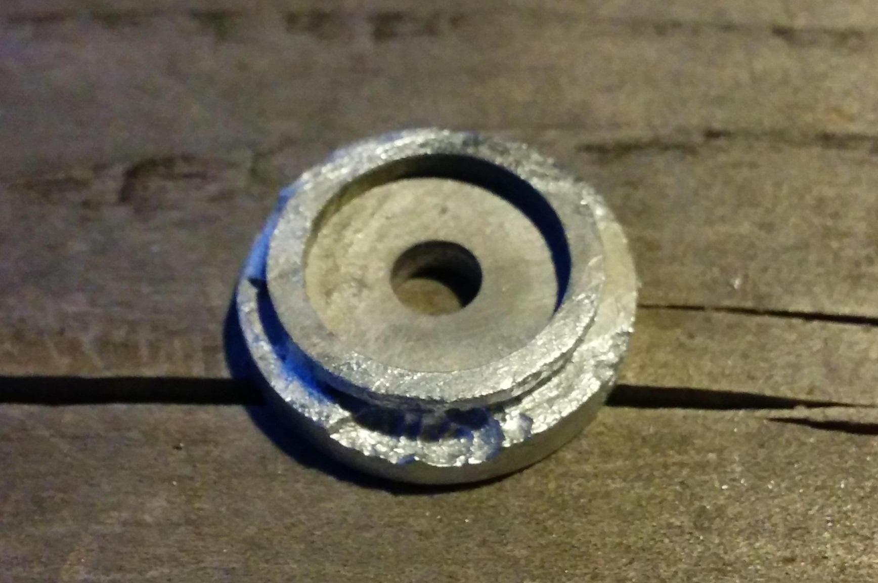
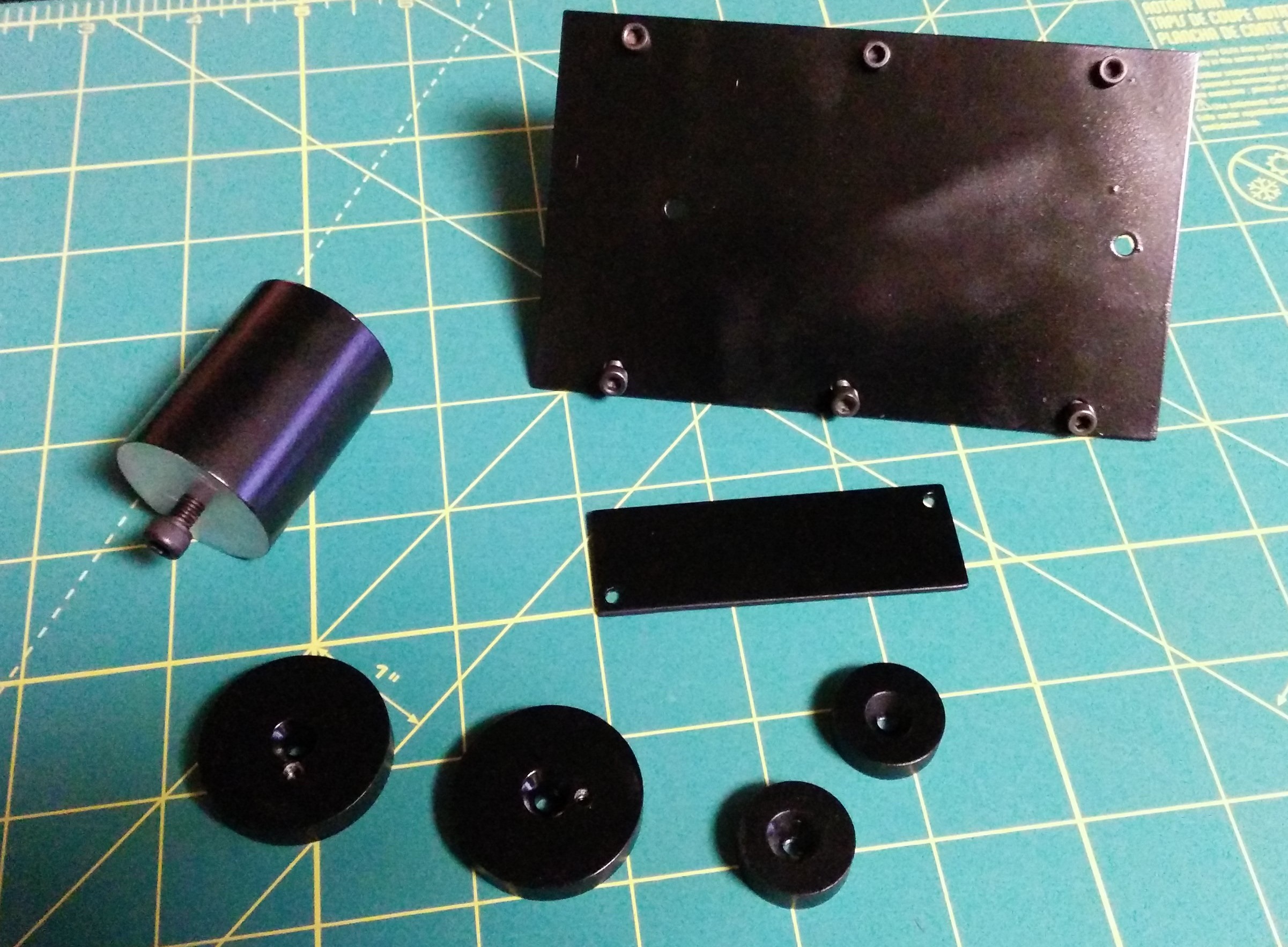
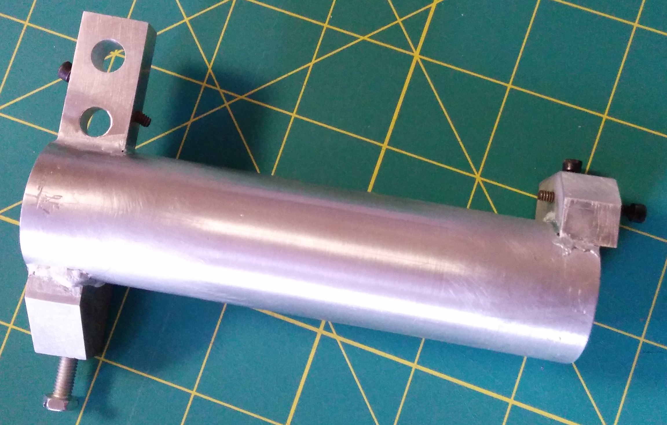
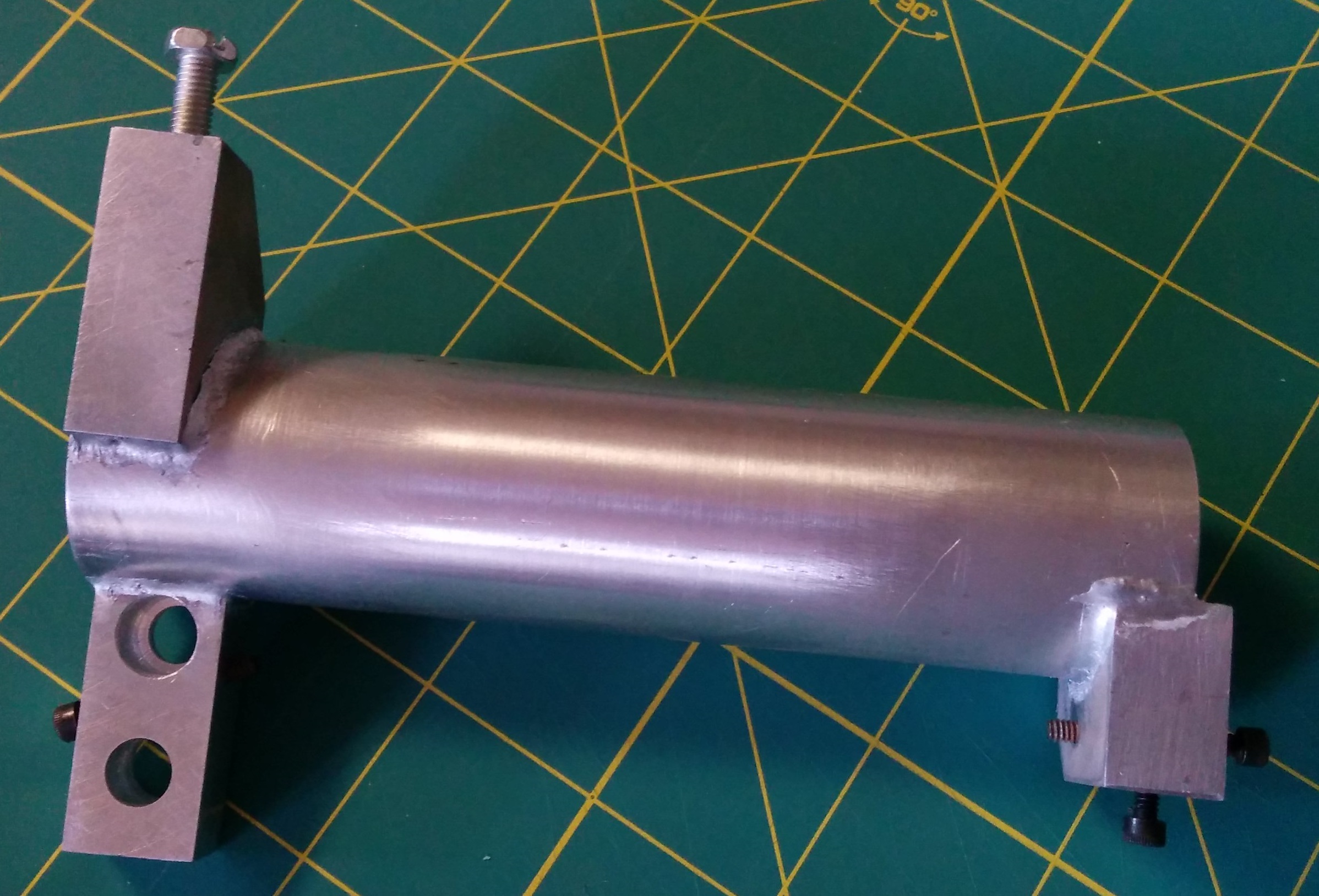
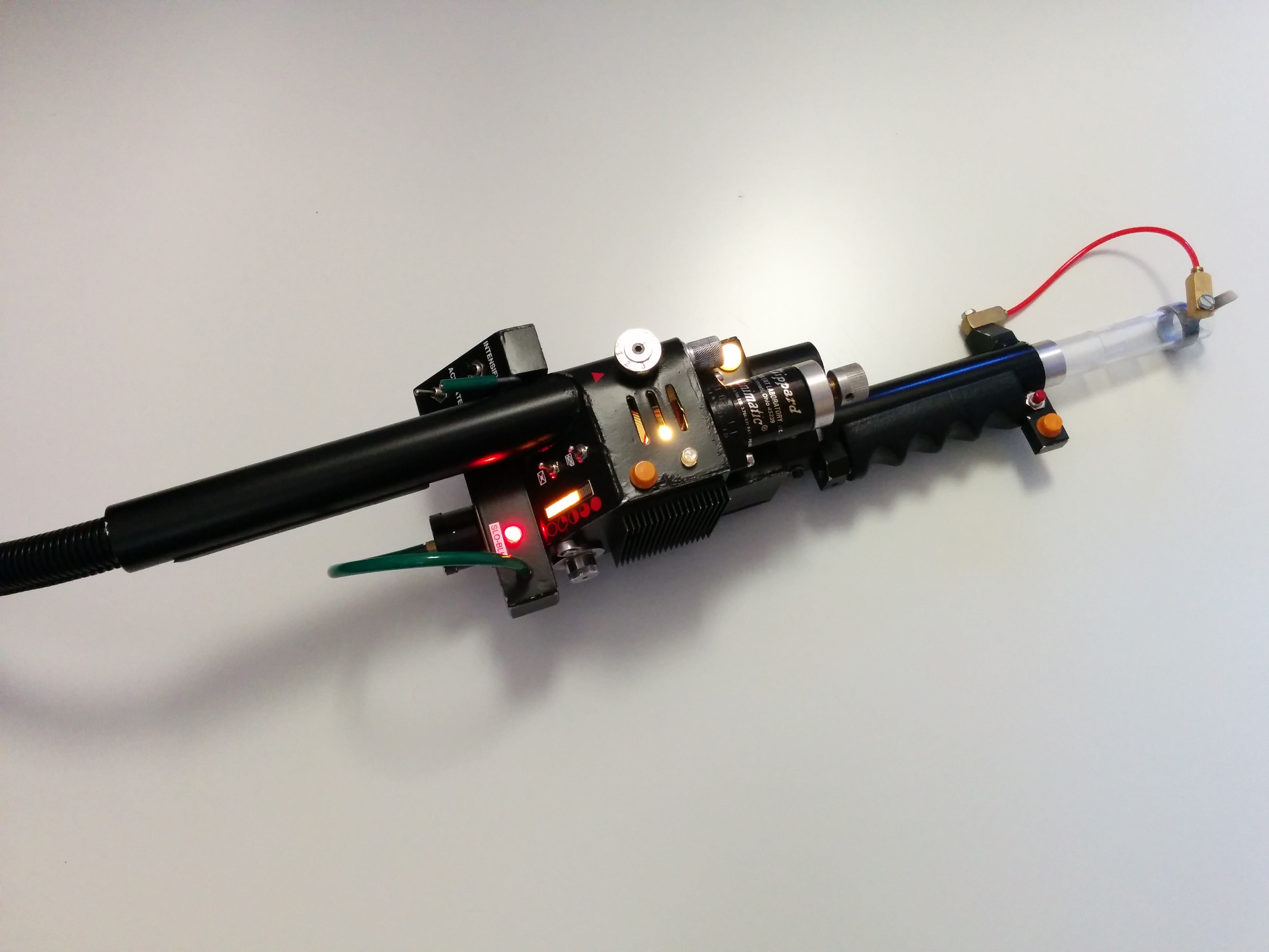
Here is a test fit of the copper rods after a quick polish of the parts:
Image


On to the banjo fittings!
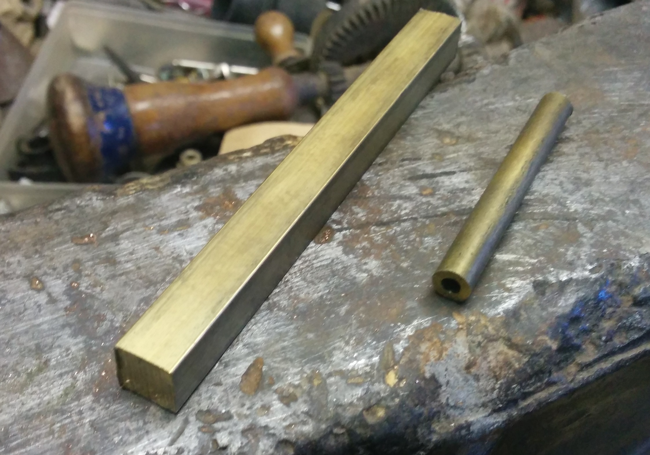
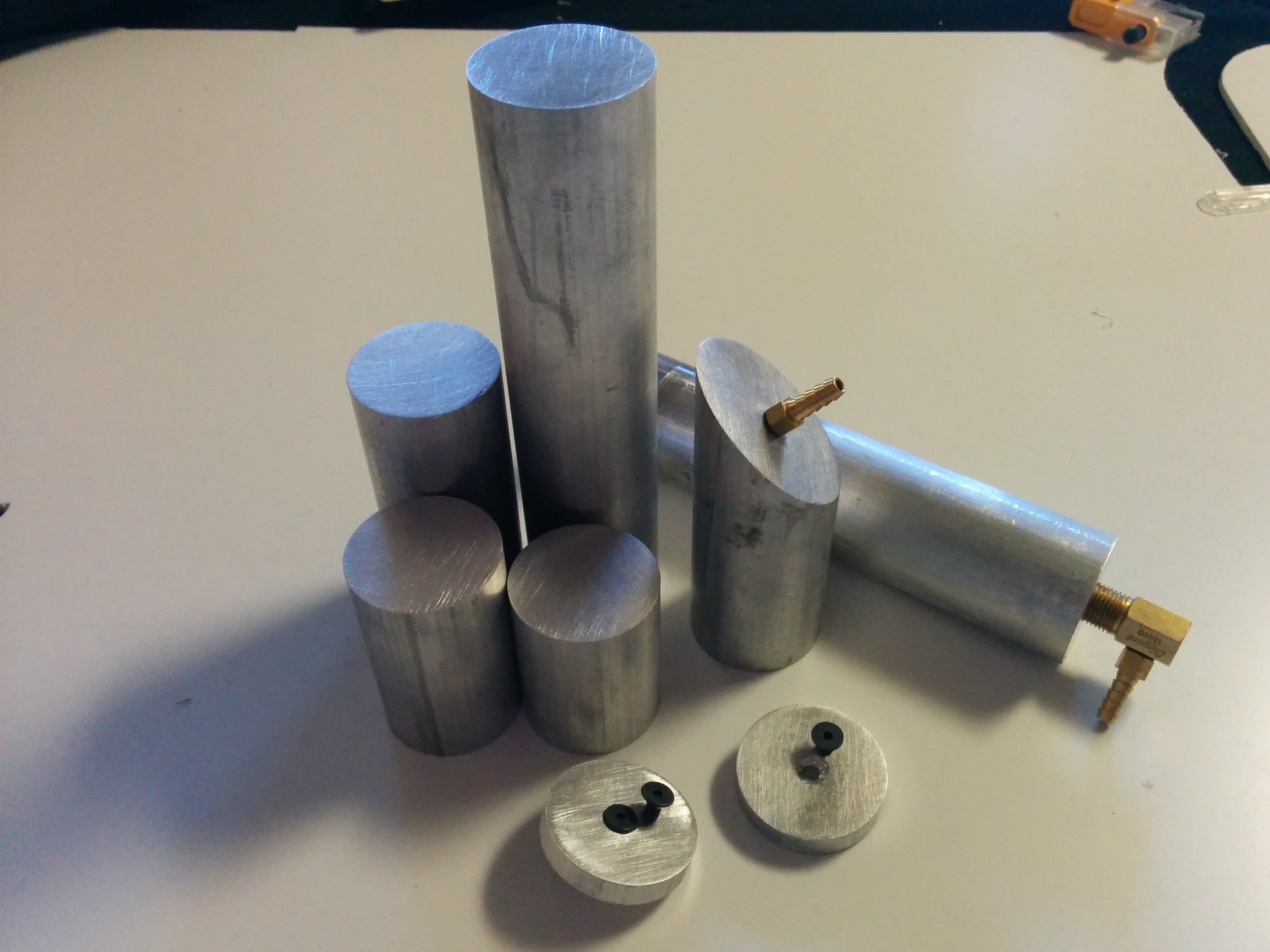
Here is my starting material, 3/8" square brass stock, and 1/4" brass tube:
Image

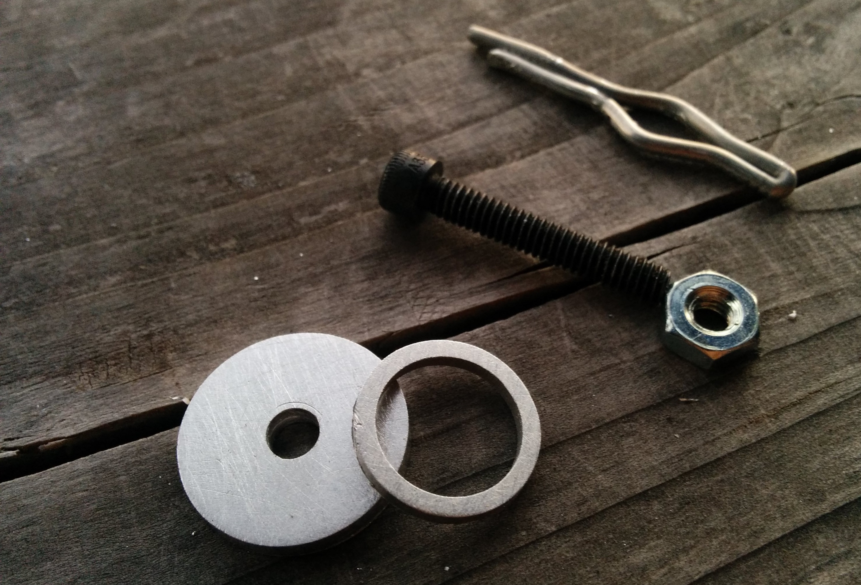
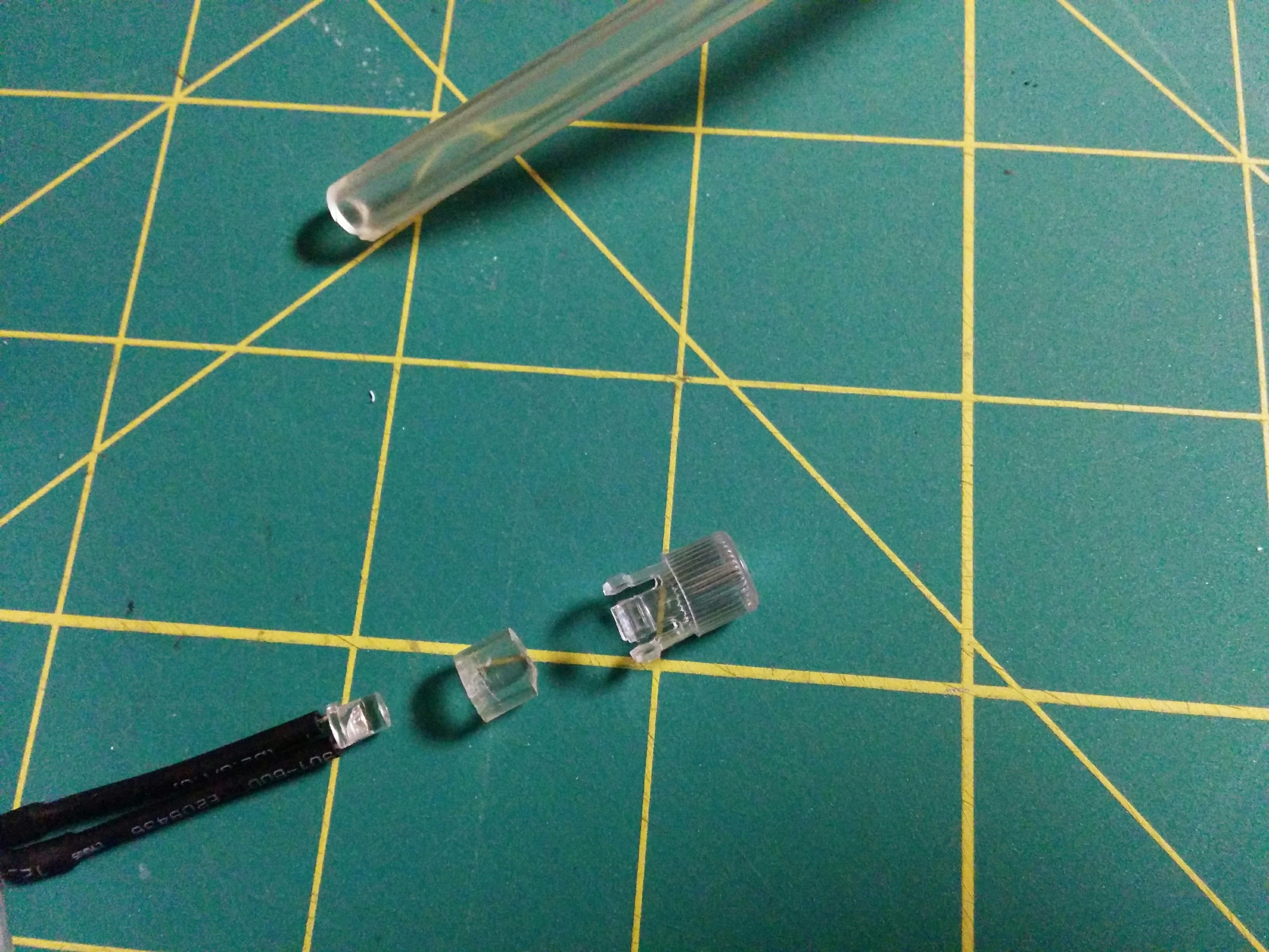
I started with the hose fittings- cut the tube to length, square the ends, and polish:
Image

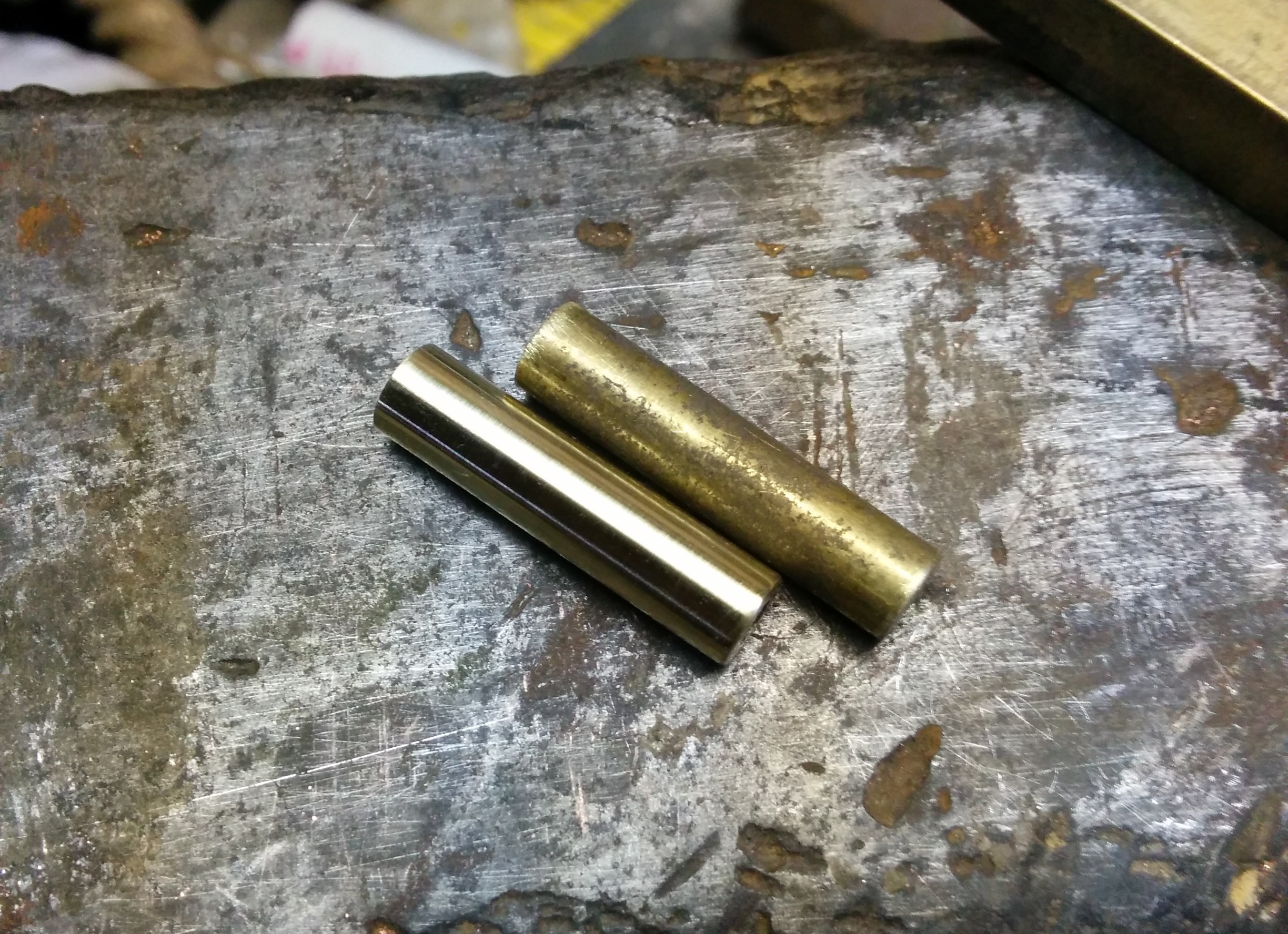
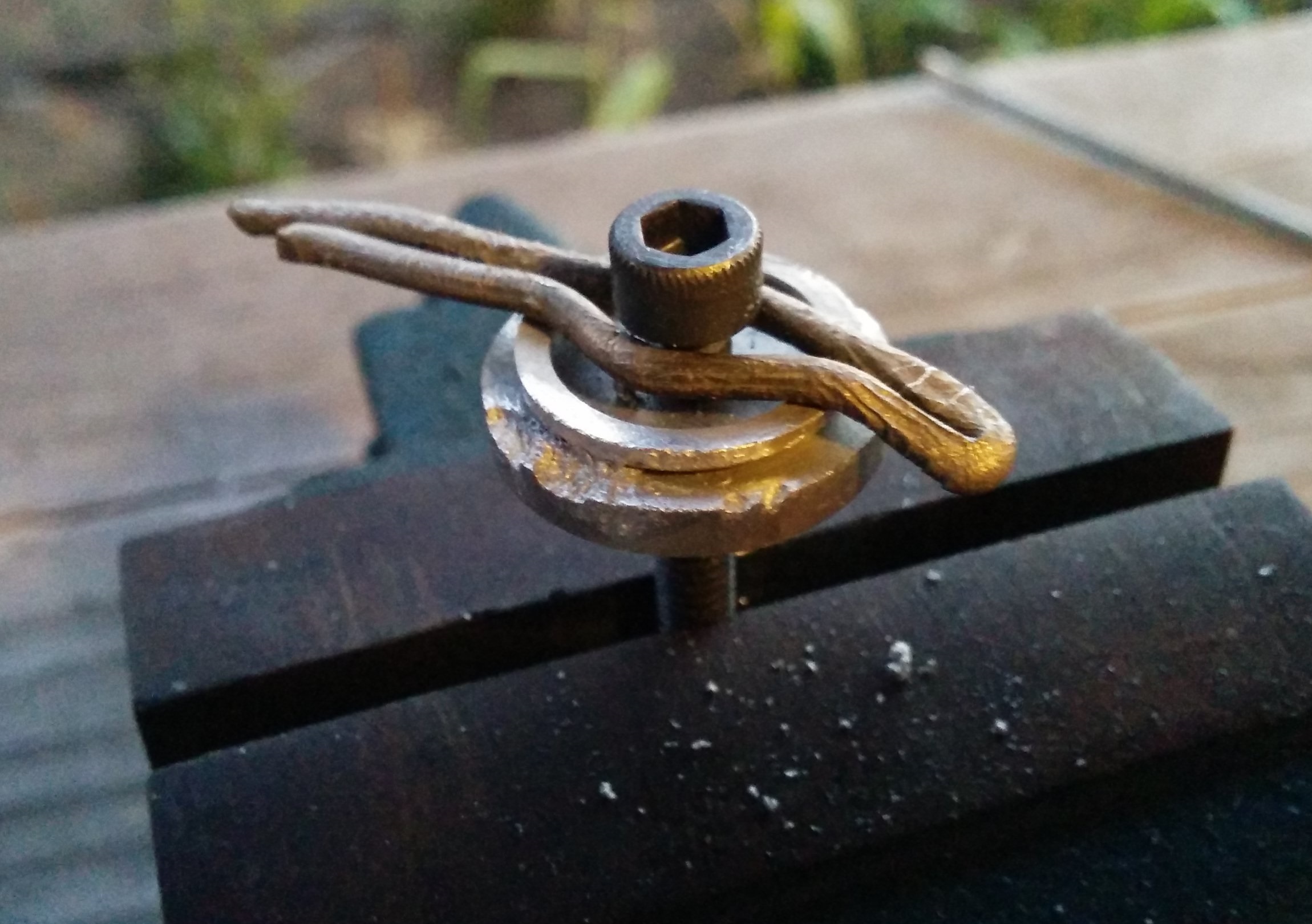
Who needs a lathe when you have a drill press and dremel?
Image
Image

The top piece has an ugly end where I practiced my technique:
Image

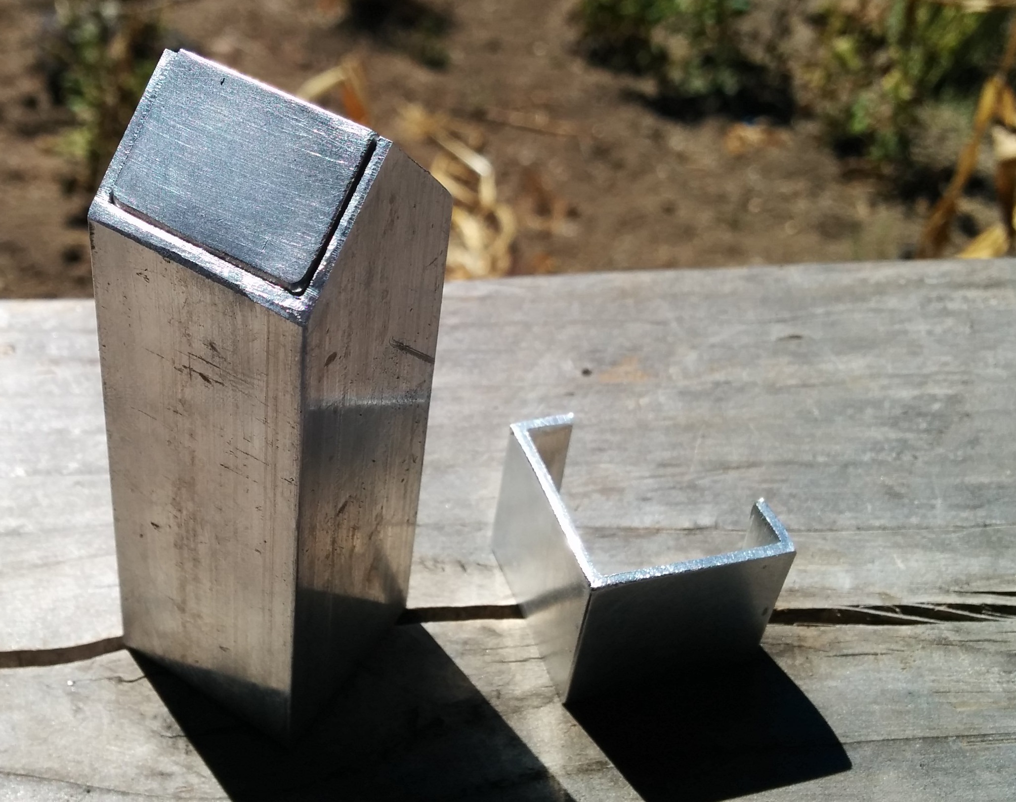
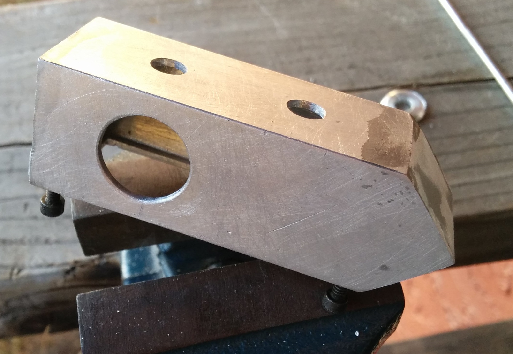
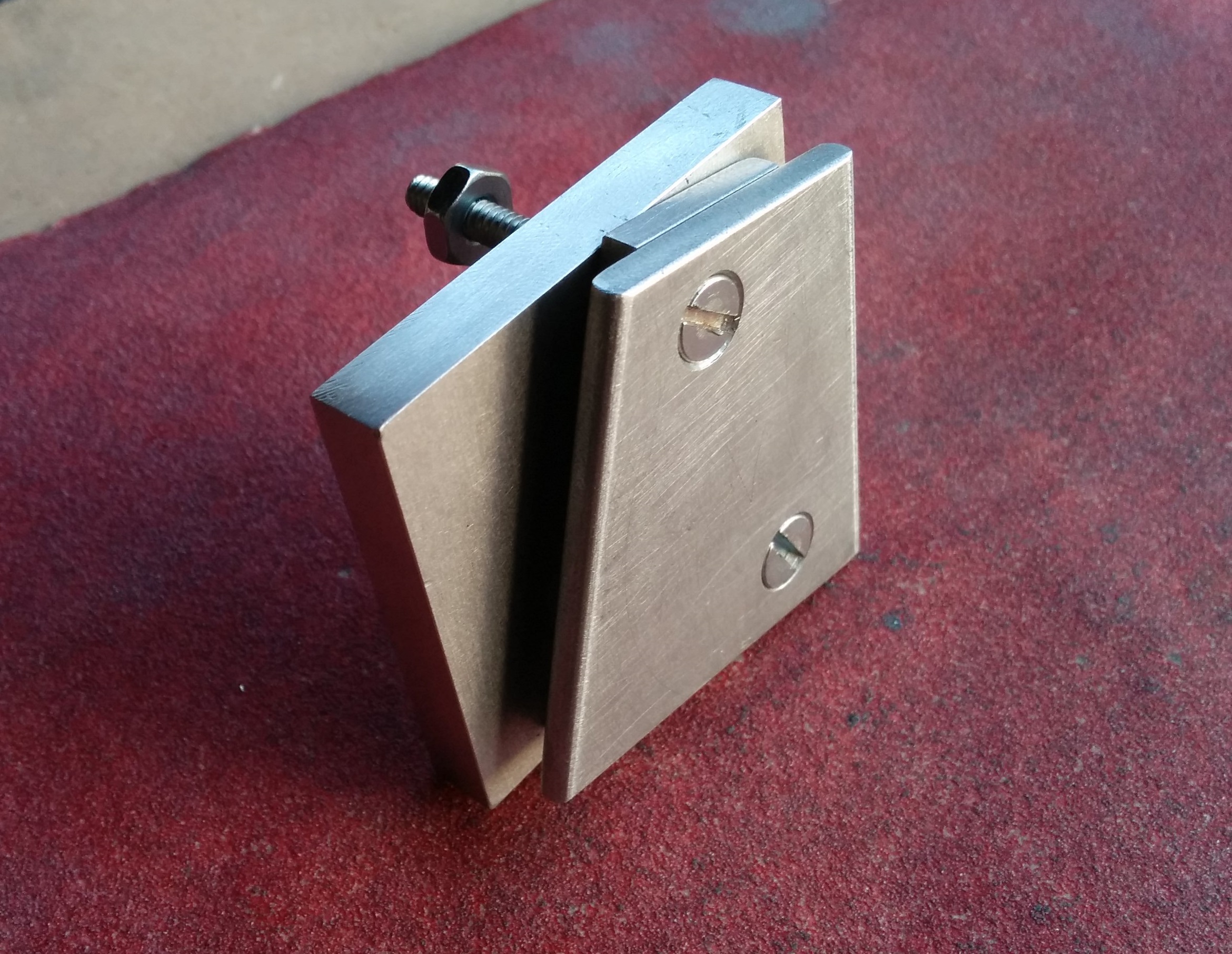
For the body of the banjo fittings, I cut the stock to length, squared the ends, etc, etc:
Image

Drilled and tapped the 10-32 hole for the screw:
Image

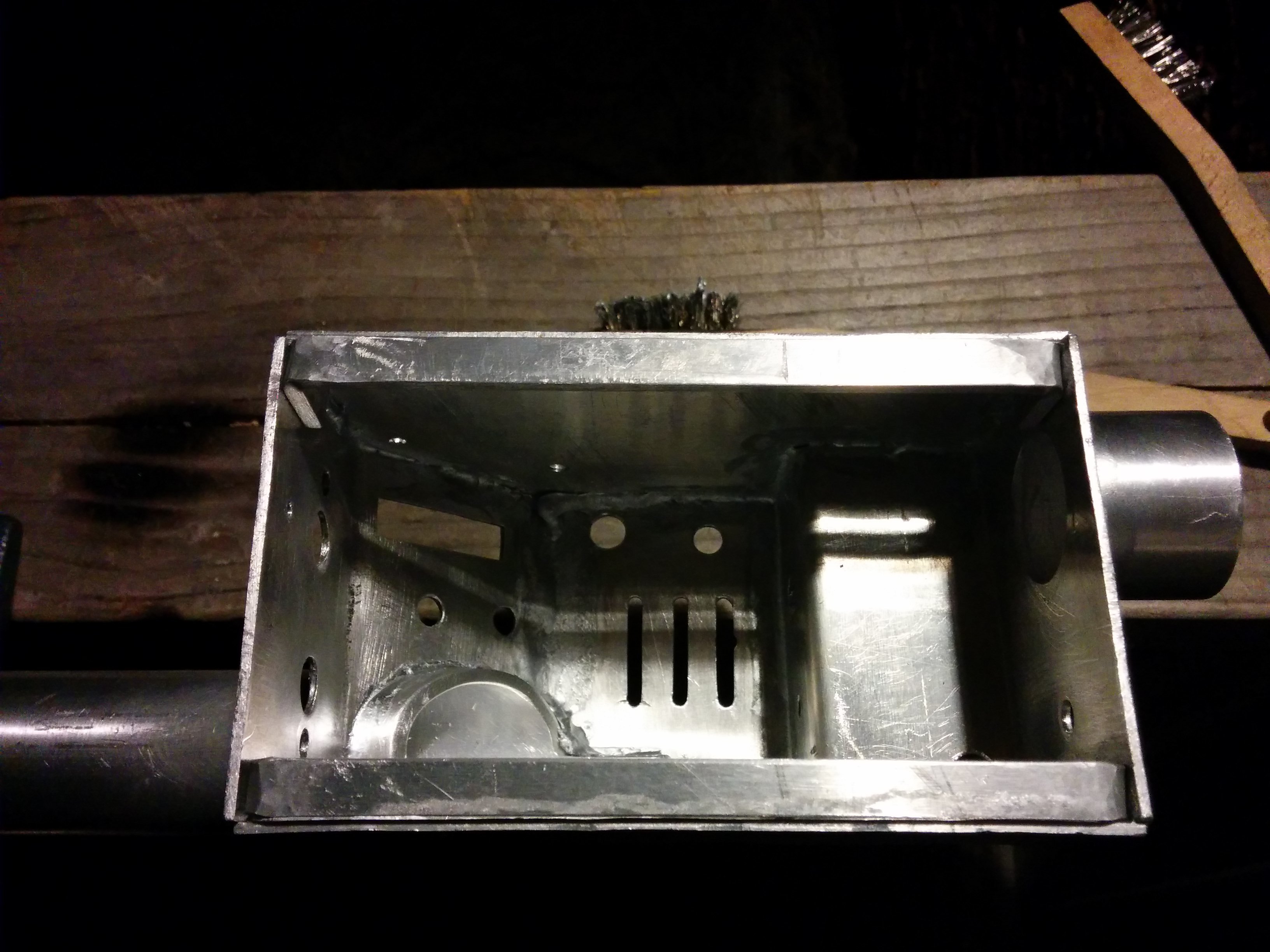
I didn't have a 4 jaw chuck (to turn the work piece), so I had to drill out the inside the hard way. I starting by finding and punching the center of the end face:
Image

Drilling out the inside:
Image

On the first one I made, I made the mistake of drilling out the inside before drilling and tapping the hole for the screw. It made
drilling and tapping the hole much more difficult because the drill bit would wander due to the variable wall thickness, resulting in a large oval hole.

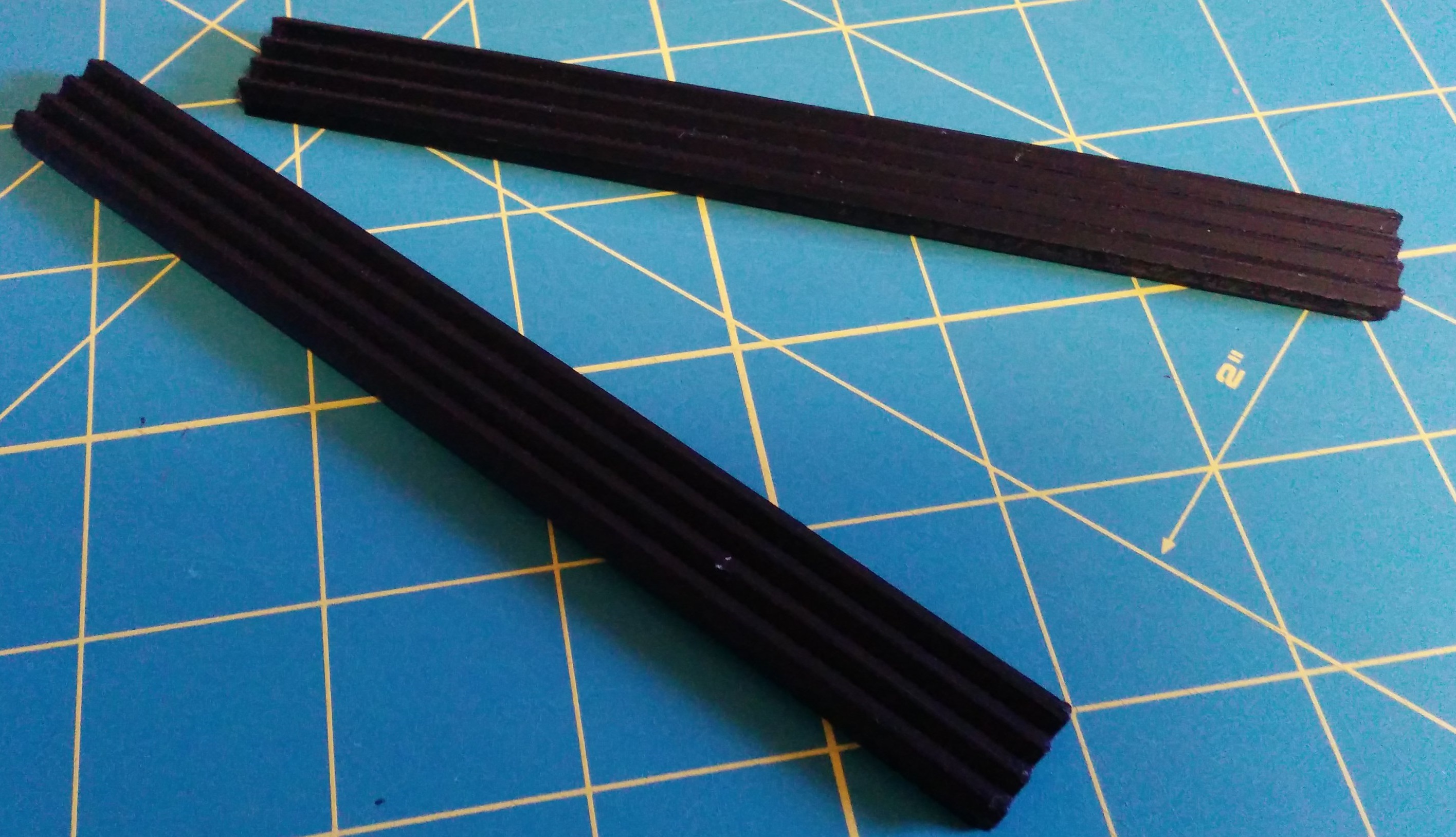
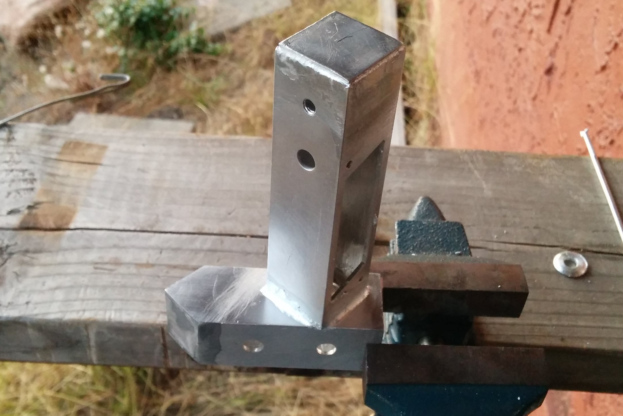
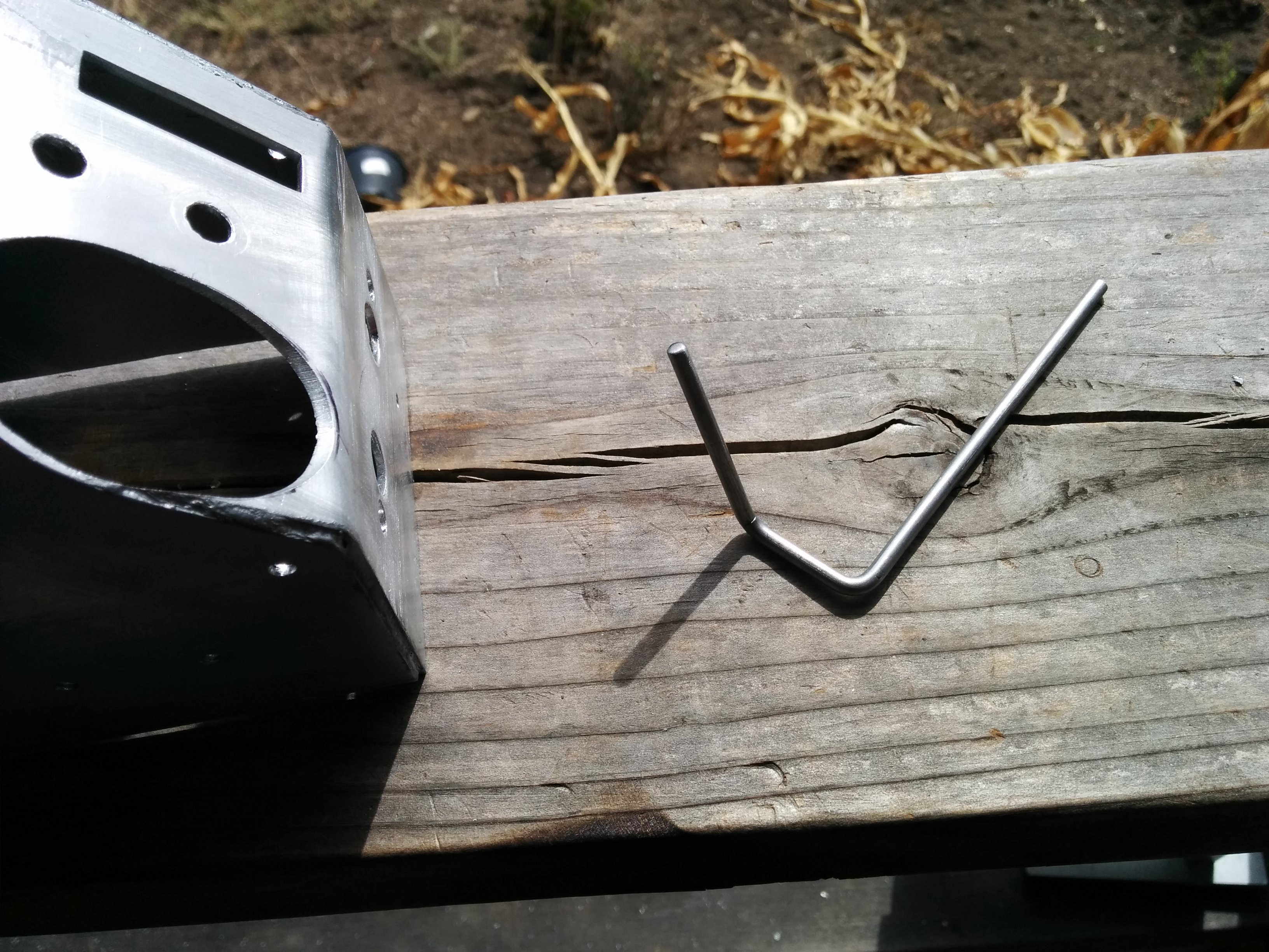
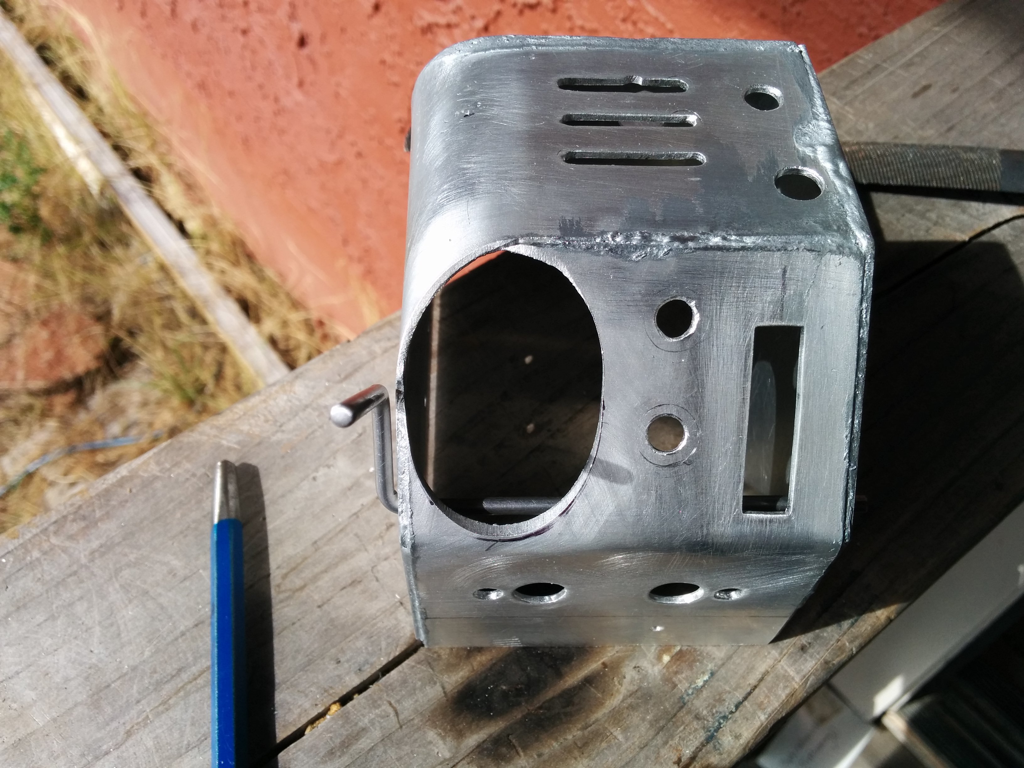
Here they are after adding the wire management holes and test fitting the tubes:
Image

Now I just need to chamfer the corners and cut the tubes in half.
Last edited by Conqueror_Worm on February 17th, 2024, 4:24 pm, edited 1 time in total.
NickoRay, alphabeta001 liked this
User avatar
By Conqueror_Worm
#4823945
Completed Legris elbows! I think I may go back and drill out the threads, they are preventing me from tightening the elbow against the trigger tip.
Image

Ion arm cap! Not complete yet (there is nothing to hold the copper rods in place). I'm trying to decide if I can get away with just super gluing them in place or if I should drill some small holes in the back and pin them in place, maybe even use some tiny set screws.
Image
Last edited by Conqueror_Worm on February 17th, 2024, 4:27 pm, edited 1 time in total.
Kingpin liked this
User avatar
By CPU64
#4823948
If you are planing on having the rod permanently attached, you could slightly flatten the end a bit so it expands, then just press it into the block. You could have threaded it, but it's too late for that option.
User avatar
By Conqueror_Worm
#4824169
Thanks NickoRay! Currently I'm not planning to paint it (i'm not sure that I could weather it properly).
CPU64, I considered those options, but I didn't think they could give me the seamless transition between the parts that I am looking for. Counterboring the cap would hide threads, but there just isn't a lot of space there, and I don't have a bottoming tap or die.
#4840358
Yikes, its August already!! The year really got away from me. Time to get back to work!
I finally got around to chopping up my 1.25" aluminum rod:
Image
That gave me my filler tubes, booster plug, PPD, front gun cylinder, rear gun cylinder, and large side disks.

I still need to improve my styrene work:
Image
Last edited by Conqueror_Worm on February 17th, 2024, 4:31 pm, edited 1 time in total.
#4841066
I didn't have a lot of time to work on the pack this weekend, but I did make a little progress. I spent a lot of time sanding saw cut marks off of little metal disks. Here is the start of my gun track disks:
Image

My goal for the weekend was to complete the side disks for the thrower. I didn't have time to paint them, but the metal work is finished:
Image
Last edited by Conqueror_Worm on February 17th, 2024, 4:33 pm, edited 1 time in total.
alphabeta001 liked this
#4841374
Thanks Nick!

I attempted to make a gun track disk tonight. The plan was to solder a very short piece of tube to a disk:
Image

I put a chamfer at the bottom of the tube so that the solder would (hopefully) stay in the groove and be less obvious. Here is how I clamped the assembly together:
Image

The wire I used in my improvised clamp was aluminum (to reduce contamination during soldering), and it melted:
Image

I replaced the wire with a galvanized steel one (the only other wire type I had), and finished soldering the piece. Since the solder I was using was around 1/8" in diameter, there was a lot of excess solder in the joint, which I attempted to remove with a steel brush while it was still molten. Unfortunately, this created a lot of pitting in the soft aluminum disk:
Image

Not pretty, but probably usable. I'll try it again later. Maybe I'll put the chamfer on the inside of the tube wall, and epoxy it together from the inside where it won't be visible.
Last edited by Conqueror_Worm on February 17th, 2024, 4:36 pm, edited 1 time in total.
#4841513
I made a lot of progress this weekend!
3D printed booster frame mat:
Image

Finished the bumper:
Image
Image

Painted a few of the gun parts (and made them difficult to photograph):
Image

It seems like the biggest challenge I have to overcome in this project is the gun body, so that was my main focus this weekend. I started with a pile of sheetmetal:
Image

Shapped the back and soldered it on:
Image

Cut a hole for the rear handle:
Image

Soldered the other side on:
Image

Getting the last piece on was a challenge. As I would solder one area, another area would melt and the solder would run off. I also had a lot of issues with thermal expansion. Sometimes parts wouldn't line up once they were hot, and sometimes as they were cooling and shrinking the solder joint would break. It took a few tries, but I finally got a decent looking gun body:
Image

Then, disaster struck!
Somewhere I lost about 1/8" of vertical clearance, which meant the clippard valve didn't line up with the mounting holes...
Image

Regrettably, I was forced to disfigure the clippard valve to regain the lost distance:
Image

It worked, and still looks pretty good:
Image

I was able to mount many of the other greebles without trouble:
Image

It's starting to take shape!
Image

I'm really nervous about the rest of soldering I have to do to the gun body (rear handle, front handle base, top knob mount, posts for bottom plate screws). I may have to use some carefully placed heat sinks to avoid melting the other joints. I'm also pretty nervous about having to cut the vent slots, and the slot for the bar graph...
Last edited by Conqueror_Worm on February 17th, 2024, 4:51 pm, edited 1 time in total.
User avatar
By Conqueror_Worm
#4843098
Thanks Alan. Yeah, the heat sink isn't screen accurate. I found it in a bin of heat sinks at a surplus electronics store, and decided it was close enough. It's a little too tall, a little too narrow, and a little too thin.

Here is a quick update on the past couple weekends. I made the end cap for the instrument bar:
Image

and soldered it on:
Image

Cut out the pieces for the V-hook and gun mount:
Image

Cut out the pieces for the gun track:
Image

Started drilling the gun track holes:
Image

I got tired of drilling crooked holes, so I picked up a drill press mount for my dremel, but the dremel doesn't really have enough horse power to drill through aluminum (it stalls with very little pressure on the bit). It produces a clean hole, and lots of fine shavings, but takes forever to drill a hole. The mount is also very flexible, doesn't hold the drill bit straight, and can only hold a couple of drill bit sizes.
Image

Soldered the front handle base to the gun body:
Image

Drilled and cut the gun vents and bar graph slot. The tiny dremel cut off disk worked well here:
Image
Image
Last edited by Conqueror_Worm on February 17th, 2024, 5:00 pm, edited 2 times in total.
User avatar
By Conqueror_Worm
#4844136
This weekend's goal was to finish the trigger box. I cut a piece of 1" square tubing to shape, then used a piece of tubing scrap to form the pointed end:
Image

Soldered it together:
Image

Drilled a bunch of holes in it:
Image
Image

and soldered it to the instrument bar:
Image

I also did some work on the gun track, V-hook mount, installed set screws on the ion arm end cap, and cut out some pieces for the front gun grip:
Image
Last edited by Conqueror_Worm on February 17th, 2024, 5:04 pm, edited 1 time in total.
alphabeta001 liked this
By gold333
#4844142
Wow, a metal super hero pack? Do you have any specific pack you are trying to rectreate from GB1?

Ps: when I ever commision mine it will be a GB1 aswell :)
User avatar
By Conqueror_Worm
#4844725
gold333,
I don't really have a particular pack in mind, I'm just sort of creating an idealized GB1 pack, but using GB2 parts when its more convenient (namely the GB2 ribbon cable). I do plan to copy the hat light colors used on the wand during the Gozer scene closeup.

The goal for this weekend was the completion of the front gun grip:
Image
Image
Image
I would have finished it, but my 4-40 tap was too short...


Gun Barrel:
Image

Gun lever:
Image
Image

Did some work on the gun track:
Image

Does anyone have any tips for attaching the hat light lens? It looks like it has a 5/16" - 27 thread, which seems to be very rare.
Last edited by Conqueror_Worm on February 17th, 2024, 5:09 pm, edited 1 time in total.
#4845373
Finished the gun track this week.
Clamped:
Image

Soldered:
Image

Finished the V-hook mount:
Image

Installed some 1/8" strips of Al in the wand so I can fasten the bottom plate:
Image
Image

The gun lever interferes with the bar graph PCB:
Image

It looks like I should be able to trim the PCB without too much trouble, or I can make the mounting slot a little longer so that the bar graph sticks further out of the wand (which would probably make it more accurate).
Image
Last edited by Conqueror_Worm on February 17th, 2024, 5:13 pm, edited 1 time in total.
#4865725
I decided to scrap the MDF pack and buy a GB fans shell. This way I'll end up with a more durable, lighter weight pack (not to mention shave a couple months off the build time). The only downside is the fiberglass dust:
Image
Horrible stuff...

This is where I left off today:
Image
Last edited by Conqueror_Worm on February 17th, 2024, 5:16 pm, edited 1 time in total.
#4868089
I've been having a lot of trouble trying to figure out how to mount the hat lights. The thread size is 5/16"-27, which is a really odd size. I even picked up a tap on ebay, and tried to make some custom nuts that would hold the hat light in place, but the hat light threads are square instead of triangular! I eventually gave in and bought a couple hat lamp sockets from GBfans. Being an older piece of electronics, they are not designed for use with LEDs, and require modification. With a little light pressure on the brass pin, the guts of the socket pop right out:
Image

There was a silicone spacer inside of the socket that should work well for holding the LED in place:
Image

Today's goal was to finish building the gun housing. This involved drilling some pilot holes to the final size, and installing the mount for the top knob. I cut the mount to the correct length, drilled out the inside (to make shaping it easier), then filed and sanded it to match the contour of the housing:
Image

Bolted to the housing for soldering:
Image

Fabricated the S-hook:
Image

Mounted S-hook and V-hook:
Image

I also finished the gun lever assembly. I didn't take any progress pictures for the gun hook retaining knob, but it was basically the same process I used to make the hose fittings on the legris elbows (drill press lathe). Today's progress:
Image

Tomorrow I install the electronics!
Last edited by Conqueror_Worm on February 17th, 2024, 5:21 pm, edited 1 time in total.
#4868156
Ok, so I didn't install the electronics. I decided to try and hold off on the electronics until I have everything "built". Then I can upgrade the pack with the electronics once I actually have a pack. I'll still install the switches and other visible components, I just won't worry about the guts until later.
Today I did a test assembly of the wand, to find out where all the mechanical issues were. For example, the barrel and front grip had a lot of slop, so I added some heat shrink tubing to improve the fit:
Image
I may have to coat the heat shrink tubing with grease or oil; rotating the front grip makes an unpleasant squeaking rubber noise...

Once everything looked good, I took it apart and painted everything:
Image
I'm really excited to start putting stickers on it!!!
I'm also really scared to start putting stickers on it...
I'm afraid that either I forgot to solder a piece on, or drill a hole, or that one of the solder joints will fail. If I have to re-solder something, it will destroy any paint or stickers that are on the assembly. Measure twice, cut once, measure twice, cut once...
Last edited by Conqueror_Worm on February 17th, 2024, 5:24 pm, edited 1 time in total.
#4868629
Stickers!!!
Image
Image
Image
Image
The dry rub transfers look amazing! Very clean, very professional looking, but they are also very unforgiving, and can be difficult to work with. I botched a couple of the transfers near the bar graph. The most important thing seems to be NEVER EVER MOVE THE PLASTIC SHEET, until you are sure that they are fully transferred. Make sure the plastic sheet is well secured with tape, and use a smooth, plastic tool (such as a pen) to rub them. I first tried using the handle of my xacto knife, but it seemed to pull and dig into the plastic sheet.
I sprayed the parts with Rustoleum Painter's Touch Clear Satin when I was done, to help hold everything in place. It helped eliminate any raised areas caused by the dry rub transfers and stickers, and made everything nice and smooth.
I've been trying to figure out a way to protect the barrel wires that pass through the wall of the gun body, something like a very tiny strain relief, to prevent them from rubbing against, and being cut by the edge of the aluminum. I decided to give grommets a shot. It looks like it should work well:
Image
Last edited by Conqueror_Worm on February 17th, 2024, 5:28 pm, edited 1 time in total.
#4869025
I couldn't resist, I had to install the electronics...
I had a really simple idea for mounting the electronics, and had to give it a shot. For the bar graph, I just attached the switches and bar graph to a piece of 1/8" thick polystyrene that had holes in the correct location, and the switches hold everything to the enclosure:
Image
Image
Image
For the circuit board, I laminated two pieces of 1/8" polystyrene together, then drilled three holes, and tapped the middle one. It mounts on the same wall as the side disks. The side disk fasteners register with the two outside holes, to prevent the circuit board from turning, and the formerly useless screw between the side disks now threads into the polystyrene. The circuit board is held on by screws that thread directly into the polystyrene, with a few washers for spacers.
Image
Image
Image
Not sure where to stick the rumble motor and barrel extender...

Mounting the LEDs to the cliplights was another item I've been thinking about for a while. Finally came up with another simple solution. I just cut a short piece of tubing that had the right ID to hold the LED, and the right OD to fit in the cliplight. It's held together only with friction, so we'll see how well it holds up.
Image

And now for the glamour shots!
Image
Image
Image
Image
Successful test.

That was just Friday night!
The rest of the weekend I worked on the pack and the belt gizmo. Some drilling, some painting, not much to see.
Last edited by Conqueror_Worm on February 17th, 2024, 5:38 pm, edited 2 times in total.

I've ordered one of these for a friend to use off […]

GB News is calling the Pink Camo Tint the last m[…]

Sugarland Express.Very early Spielberg movie,it's […]

Also probably different release dates. USA[…]