User avatar
By GBfan77
#4822758
Since I put it together a year or so ago it's done the job for me but It's starting to show a little wear and tear. After attending my first sci fi convention it became clear to me that a few things needed to be upgraded and/or replaced.

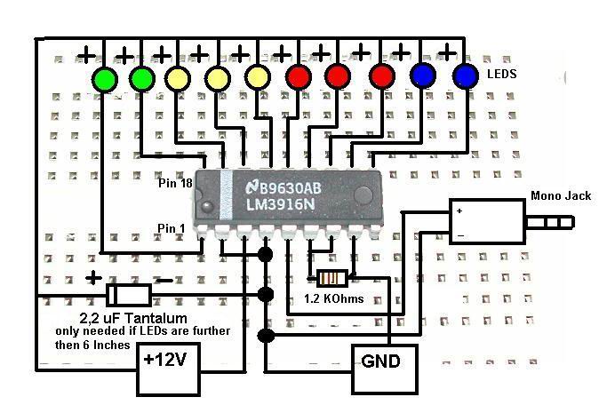
First step in that process was to buy a rubber heatsink from Nickatron. Found out in the most incovenient way that resin is a little brittle and tends to break if you don't give your wand enough padding while it's in your suit case. The next planned upgrade will the audio system. As I found out in a crowd a speaker without an amplifier can' t really produce enough sound to be heard over people. I don't want to overhall the whole system because that would involve ripping apart the whole pack. I've found a schamatic online for a Nine Volt Amp but I can't understand the diagram. It looks greek to me.

Image

If anyone can give me a hand in that regard I'd appreciate it.
#4823456
Grimmy GB wrote:I'm not sure where your understanding in electronics is, but here's a good start to understanding the symbols.

Pretty much the only way any electronic schematic makes sense to me is if it's something like this:

Image
#4823477
I understand the schematic, do you have any specific questions?
How are you planning to build it? Are you going to leave it on a breadboard or solder it together?
When building a circuit, I always find it helpful to print the schematic. Every time I make a connection I trace over it on the print with a colored marker. It helps me keep track of which connections have been made.

Here is the LM 386:
Image
The pins are numbered like this (the circle/dimple on the white stripe always indicates pin 1), just match the pin number to the number on the schematic:
Image


The potentiometer (or variable resistor), labeled 10K, could have several appearances. The arrow is the middle pin, the other two are interchangeable:
ImageImageImage


Reistors have two wires, and can be connected either way:
Image
Image


The capacitors in the schematic are polarized, one wire is positive, one is negative. The symbol has a + to mark the positive side, but the capacitor has a grey stripe to mark the negative side:
Image
Image


Batteries have a + and -, the + is marked on the schematic.
Speakers can be connected either way.
The switch will depend on the type you buy. Common ones have from 2 to 6 pins. Any toggle switch should work, but a single pole, single throw (SPST) will be simplest (only two pins, like the schematic).
The "audio in" should be fairly straight forward, you can tell from the schematic which wire to connect to the outside and which to the inside (it may not matter, but don't quote me on that).
Ecto-1 fan liked this
#4823875
Thanks man, I appreciate the help. I plan to solder the whole thing to a breadboard (Why it's called that I have no idea).

Other than the electronics I also plan to replace a few parts that I've been less than satisfied with. Notably the Powercell and Crank generator/gearbox assembly. May also tackle the cyclotron spacer. Knowing what I know now I think I can make improvements in these areas. Speaking of Cyclotron spacer I was thinking of adding something from The Real Ghostbusters since my pack isn't 100% movie accurate anyway. It's a box that has a series of lights and switches (I don't know what you guys would call it).
#4828152
First upgrade part worth showing off. The ion arm and Ion Cap.
Image
Image
The dots are from where I covered the screws with JB putty. The Ion cap I bought off ebay. I think It's the Ghostbusters 2 type, though I have to check to be certain.
User avatar
By GBfan77
#4828156
Demon Vice Commander wrote:
GBfan77 wrote: I think It's the Ghostbusters 2 type, though I have to check to be certain.


Some of the Hero packs in GB1 and GB2 either have the square fitting on the end cap or the hex fitting on the ion arm body, so the version you have is technically accurate to either film. :)
I did a quick search and it looks like I have a GB2 style Ion cap, which is fine considering the ribbon cable currently on the pack is also a GB2.
#4828206
DVC, I didn't think any GB1 pack had the hex barb on the arm, I thought they were all on the cap with the square barb.

Did you ever finish working the amp? With the LM386, it alteady has a 20 v/v amp gain, and you can play around with that by changing some resistor values across pins 1 and 8. It's a versatile little chip.

http://www.ti.com/lit/ds/symlink/lm386.pdf

The setup above is copied straight from the data sheet for the 200 gain setup.
#4828207
Hijacker wrote:DVC, I didn't think any GB1 pack had the hex barb on the arm, I thought they were all on the cap with the square barb.
I may be wrong but I'm sure the super hero pack has the hex barb on the ion arm

*EDIT* Found the picture in Julz Super Hero pack thread. Zoomed in but you can make out the Clippard Hex barb on the Ion Arm

Image
#4828209
Hijacker wrote:DVC, I didn't think any GB1 pack had the hex barb on the arm, I thought they were all on the cap with the square barb.
Here's the Top view of the ion cap. It's off because one of the holes drilled for the screws is off. I need to re-drill them anyway.
Image
Hijacker wrote:Did you ever finish working the amp? With the LM386, it alteady has a 20 v/v amp gain, and you can play around with that by changing some resistor values across pins 1 and 8. It's a versatile little chip.

http://www.ti.com/lit/ds/symlink/lm386.pdf

The setup above is copied straight from the data sheet for the 200 gain setup.
I never got a chance to due to a financial situation but it has since been resolved and I'm looking to build it. I'll check out the Data sheet. Thanks.
#4829588
Found an Amplifier I think I can build.
http://www.instructables.com/id/Make-a- ... Amplifier/

Image

We don't have a Radioshack in Canada anymore, so whats is the best site to order the parts for this project? Oh, for those who don't want to click on the link for the Parts List:

1- LM 386 semiconductor (IC)
2- 100 micro Farad capacitor
3- 220 micro Farad capacitor
4- 10 ohm resistor
5- 5 kilo ohm variable resistor
6- 100 ohm variable resistor
7- 0.01 capacitor
8- 0.047 capacitor
9- Wires
10- 9V Battery clip
11- 9V Battery
12- 3.5mm stereo jack male
13- 3.5mm stereo jack female

I think I might have the IC chip for this project (bought it years ago) and I think I can get away with not using the male and female stereo jacks as it's going to be soldered directly to the sound chip.
#4829977
Well, it's installed. A little tricky as the measurements of my pack are not 100% accurate but I think it turned out okay

Image
New plug. Debating whether to keep it silver or paint it black. I'll be fixing where the wood is chipped later with JB epoxy.
Image
#4830635
Replaced the stack of washers I had for a Bumper Shock mount with a dollar store faucet attachment. Because I don't have time to install an amplifier setup the sound from the speaker will go through the hole in the middle of the attachment.

Some may point and say "THAT'S NOT ACCURATE."

Well, neither is the bumper. I do plan to paint the white areas silver.

Also added a switch box for activating my sound chip. Where I had it Originally made it too hard to get to when I was wearing the pack.

Image
#4830639
I like how that switch looks on the side, it's unique, but I might be concerned about bumping into things with it, and accidentally turning it off (unless it's just cosmetic, so then carry on and ignore me)... Otherwise, pretty good scratch build! Love that you're taking the time to learn the electronics and building it yourself!
#4830642
pyhasanon wrote:I like how that switch looks on the side, it's unique, but I might be concerned about bumping into things with it, and accidentally turning it off (unless it's just cosmetic, so then carry on and ignore me)... Otherwise, pretty good scratch build! Love that you're taking the time to learn the electronics and building it yourself!
I don't think it'll be an issue, but then I won't know for sure until I take it out in public. I do plan to integrate into the cyclotron spacer better than the way it's set up now. I got the idea for it from The Real Ghostbusters Pack. I think it was the killerwatt episode where Ray activates his pack by pushing a button that was located in that area.

The other upgrades I plan to make will have to wait until Summer . There's a sci fi Convention taking place at the end of the month and I don't want to be in a situation where I've got the pack apart , screwed something up and I don't have the time or parts to put it back together again.
    The Video Game Lifegard

    Chris Hunt in the Facebook Group 3D Printed Ghostb[…]

    We're bringing you the latest updates to the GBFan[…]

    The amount of people participating in the milest[…]

    This is awesome, One time. I love reading explanat[…]