This is for other Ghostbusters Props that don't fit into the categories above.
User avatar
By Shwalamazula
#4809979
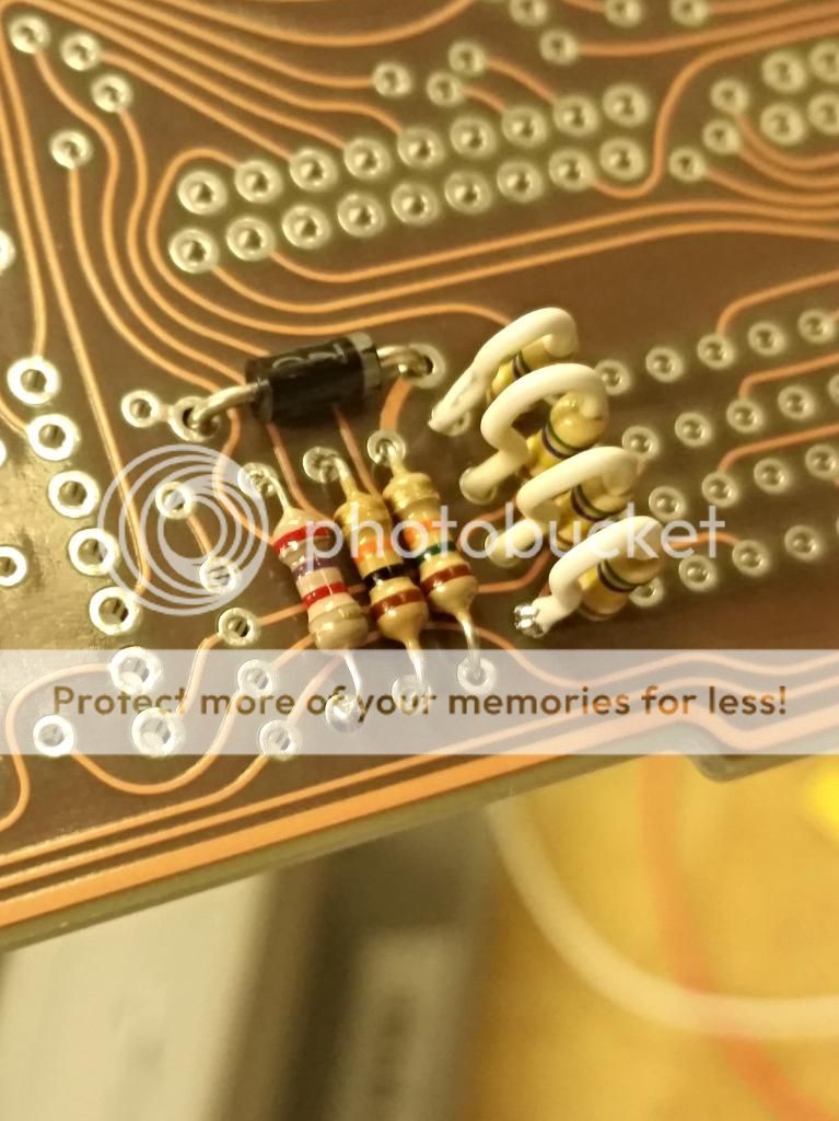
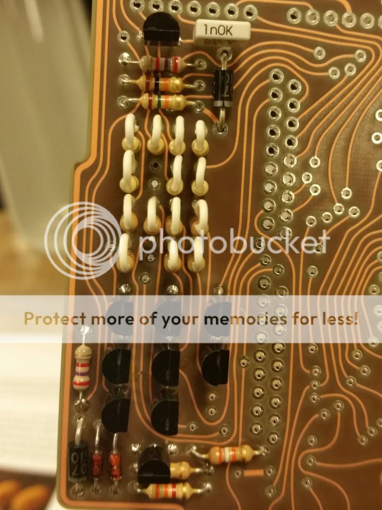
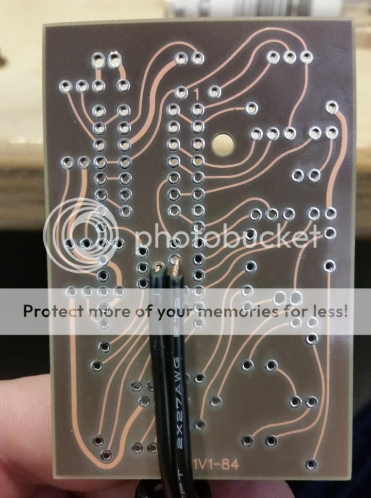
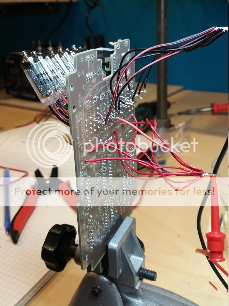
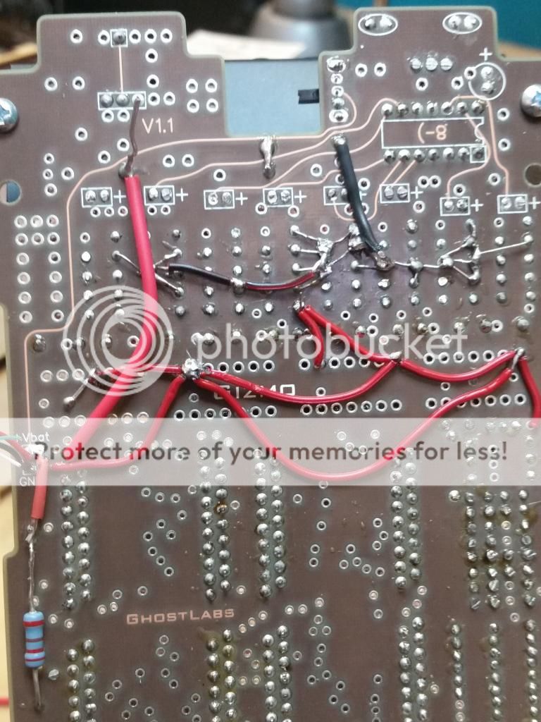
I am starting my first piece of GB hardware. I ordered a Belt Gizmo from Doug and am going to start building it up over the next week or two.

I figured a Proton Pack would take me a few months to build and is a bit pricey with a housing move in the works. There was a tossup between a Trap and a Gizmo. The Gizmo seemed like the easiest thing for a first build.

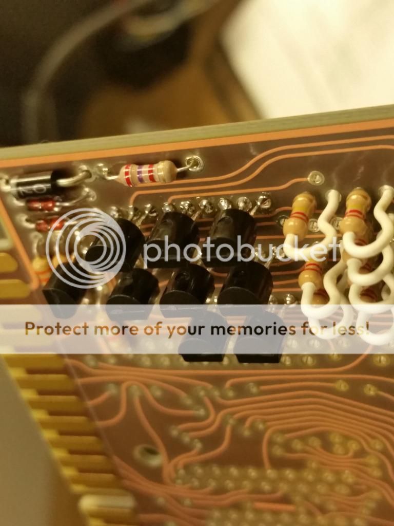
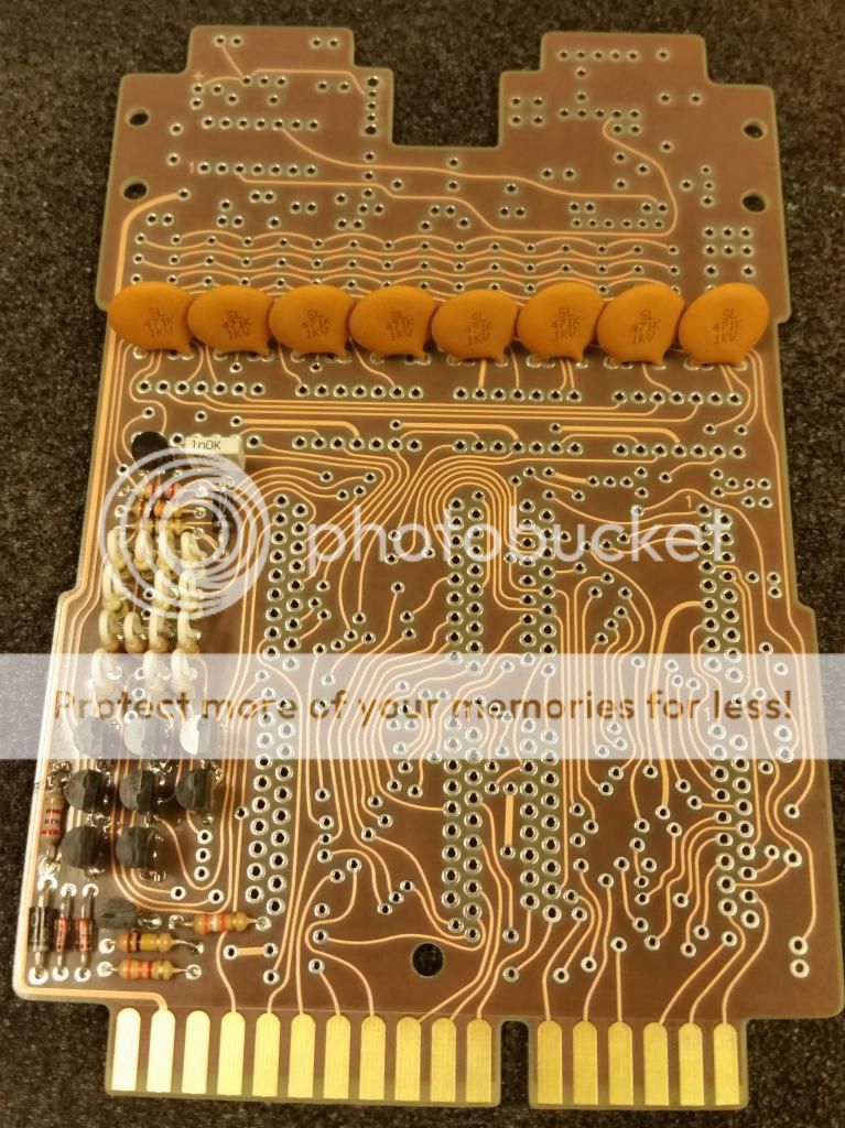
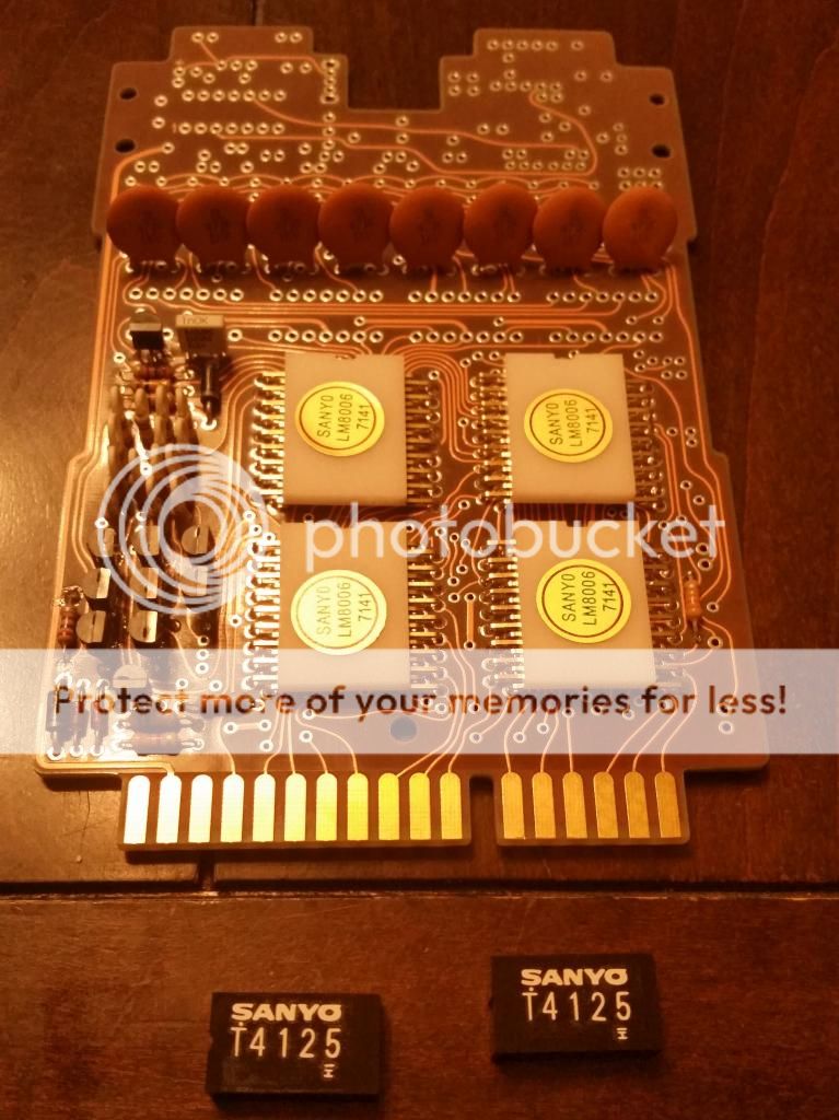
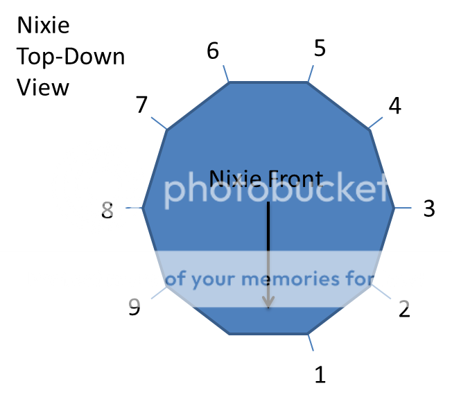
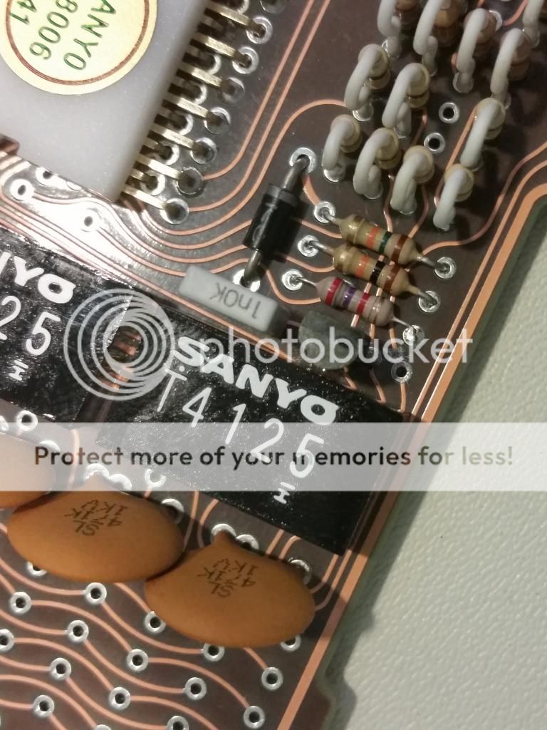
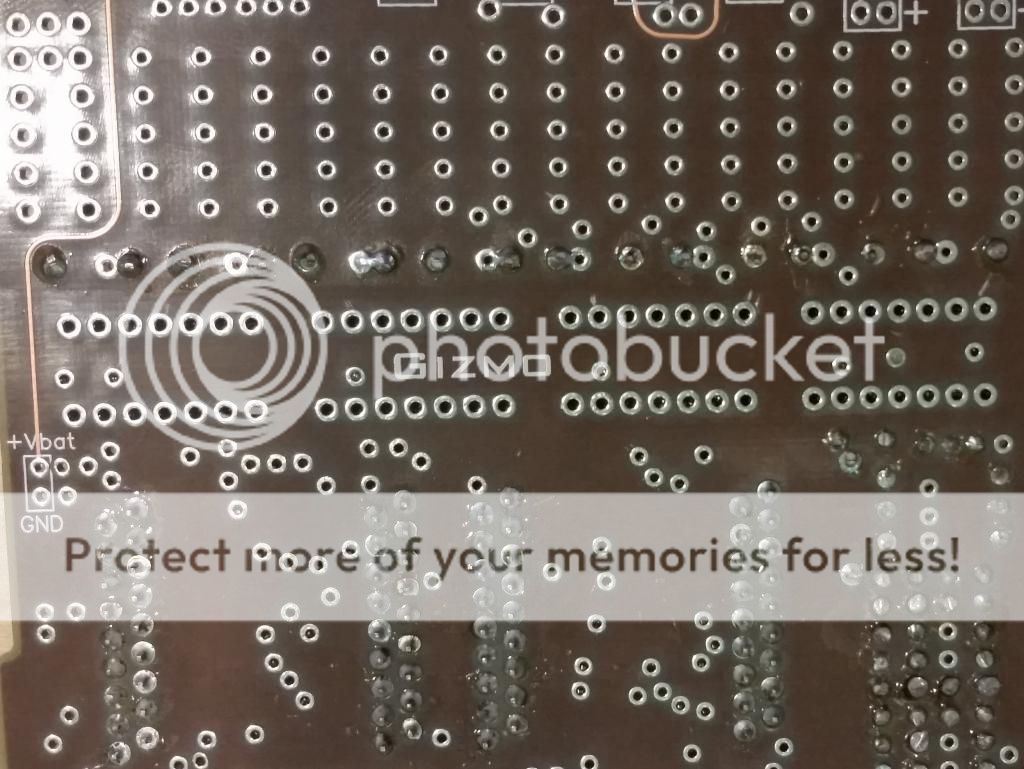
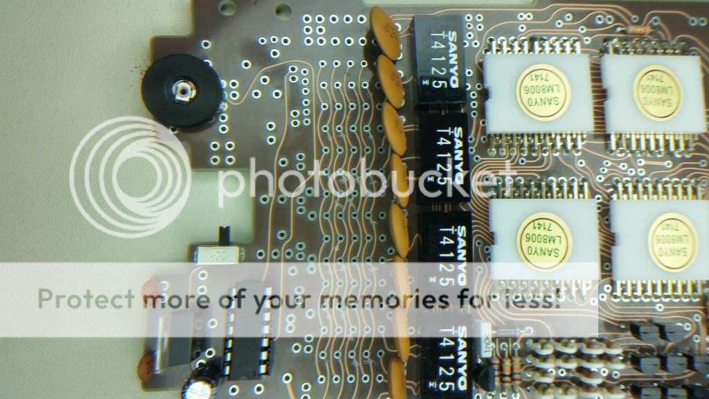
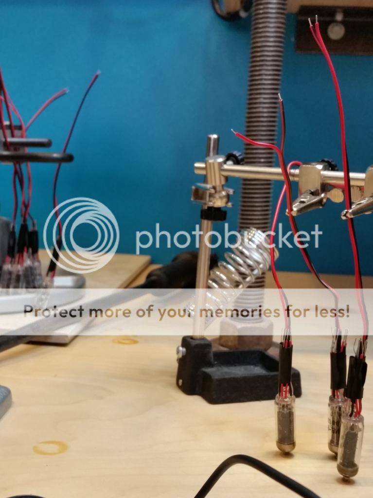
I am looking at modifying Doug’s build and adding a speaker to the board. I am not sure if I am going to attach it to the back of the board, to the daughterboard thru the connecting cable, or hide it under the ICs. My plan is to have the speaker wired to the last Nixie with a switch (im sure the sound will eventually become annoying). With the speaker wired to the last Nixie, I will have a steady beeping that will be synchronized with the pulse of the tubes to sort of emulate the PKE Meter. I am trying to figure out a way to make an override for the POT so that I can control it from an external lead without touching the board. This is going to be a fun build.
User avatar
By Shwalamazula
#4810981
I shall post some pictures today. Had a mini freakout yesterday putting the first of the 4 big IC headers on the board. I did one side before starting on the other side for one of the chips (supposed to do the outside headers, L&R, then the inside headers).

This made it so I could not fit the headers on the board properly because the plastic used for distance and placement was sitting right on soldered headers. I had to do some clever soldering and bending to fix it. I did correct the headers and now know how to properly set them.

I felt so silly because I had read the instructions front to back about 3 times before even starting the build.
User avatar
By Grimmy GB
#4810982
Installing the headers are the worst!!! I wish I had been able to purchase a full Doug setup. It's like marshmallow crème filling for GB donuts...
Will be waiting on the pix :)
User avatar
By Shwalamazula
#4811094
And the vertical resistor bank.

Image

If you are working on a vice, spreading the leads helps to apply some tension to the circuitry and helps to hold the components in place.

Image

And the completed bank.

Image
alphabeta001 liked this
User avatar
By Shwalamazula
#4811479
Now that the vertical resistors and diodes are in place, time to add the transistors.
Image

Here they are all aligned all pretty like.
Image

With the transistors in, I can add the disc caps and then on to the ICs.
Image
User avatar
By Shwalamazula
#4811480
Now for the ICs. This bit had me confused and a little miffed when I realized I messed up the first one. Once I learned from the first one, I did the other 3 properly. Sadly, for me, there was more headbanging to follow.

First I mess up and put an inner header strip in before the outers are in.
Image

As you can see, I am a wee bit boned here.
Image

But not to worry too much. I put the last header string on at an angle as close to straight as possible while leaving the pins at the right height.
Image

A little patience and bending, and the header is in and aligned like I didn't even biff it. Go me!
Image
User avatar
By Shwalamazula
#4811481
After learning from my mistake on the first set of headers, I finished the other 3 properly, outside headers then inside headers. This is where headbang number 2 came in. The plastic holding the headers together has no clearance to be removed. I tried prying the pins up with all kinds of tools. I made a small shiv that I could squeeze under the plastic to try to bend the pins up enough to release the plastic. No luck there. I even tried using my side cutters to clip away at the plastic. That was little help as well.
Image

I ended up taking a dremmel to the plastic (nailing a bit of the pins in the process). I figured, the inner pins will be under a chunk of acrylic anyway, who cares if my pins look crappy in the middle? The end result wasn't bad at all.
Image

After epoxying the ICs on the pins, there is no evidence that I was getting grindy all up on my board.
Image

While waiting on the ICs to set, I got to work burnishing the black ICs. This wasn't too bad. I cleaned the surface of the ICs and (as Doug suggested in his instructions) put the ICs on tape so they wouldn't move. I used a toothpick to do the burnishing because a toothpick is a semi hard surface but wont scratch things. It also allowed me to perfectly trace the graphics, leaving me with little to no residue. Any stray sticky stuff was easily taken off with a dry Q-Tip.
Image

I epoxied the ICs down and aligned them. I highly reccomend this Loctite Epoxy. It takes about 6 minutes to set and in that time you can wiggle and move components all you want. After it sets, good luck removing it without breaking stuff. So now I have a happy board and my next bit is installation of the LED circuitry and Nixies.
Image
#4811503
Looking great. Using epoxy on those ICs is the way to go. I used superglue and it set instantly. I was like :shock:
#4812599
Working on the Gizmo and am at the Nixie stage. The Nixies that came in the kit look really cool. Too cool actually. I was curious if they actually worked. I hooked one up to a 9V and holy cow, it worked! I am going to try and see if there is a way I can light the Nixies rather than use the LEDs for the build. Or, perhaps, do both. This is so exciting!

After some tinkering, I found out the pattern to the Nixies in this kit. I hooked the leads up to a 9V battery and went thru the permutations to figure out what circuits make which patterns. It wasn't terribly hard to tell the primary power lead (1) because of how the board and filaments were layed out.

I am using this as my reference for the circuit designations.
Image

Lighting up the Nixie, the following patterns were seen.
Image

And here is a breakdown list of the circuits that need to be tied together in order to get a pattern. Unless displaying nothing, CIRCUIT 1 should ALWAYS be alone, either by itself on the positive end or by itself on the negative end. I tried blending other circuits together and the result was a very dim light and a ton of heat evolution.
Image
#4813020
LED control circuitry is now installed.
Image

Here is a closeup of the circuitry
Image

After the control circuitry was installed, I started prepping the nixies. The instructions call for gluing the LEDs to the nixies in order to light them up. As I mentioned before, while playing with the LED and nixies, I found that the nixies are functional.
Image

So rather than glue the LEDs to the nixies right away, I only concentrated on prepping the nixies for wiring. I will still add the LEDs later but at the moment I am only prepping the nixies. So here is one of the nixies in the kit.
Image

After getting all of the shrink tube on the nixies, they get nailed with a heat gun. Be careful when you hit these with the heat gun because if you hit it at the wrong angle, you loose your shrink tube to the ether.
Image

Behold! My nixie army is nearly complete!
Image
alphabeta001 liked this
User avatar
By Grimmy GB
#4813066
Looking to forward to seeing what you pull out of this using only the nixies instead of the LEDs. Are you possibility going to spell something? In another thread, someone spelled "nOgHOST" as seen in one of the RGB episodes. It was with nixies, I just can't remember if they programmed them that way or used inserts.
#4813129
I want to tie the nixies and the LEDs together. This way I can have the message, the LED pattern, or both. The nixies will be tied to a switch.

I think I am going to have the nixies say "-bustin-". I may go with the "nOghosts" but I'm not sure. I am not going to have this IC controlled, once I decide on my message, that is it. I'm sure the board can be modified to have the tubes micro controlled; I may do this in a future build. Pin 1 will be tied together to V+ and the negatives I need for the letters will all be sunk to V-. I may have to swap out the 9V for a different power supply, maybe a lithium ion (or use 2 separate power supplies).

Doug was kind enough to send me the specs for the nixies and their operating voltage is a nominal 4.5V with each segment pulling 20mA. "-bustin-" would be 23 segments. That turns into 460 mA constant current draw. At 4.5V, that is 2.07W.

A standard 9V has a capacity of 500-600mAh. Knocking that down to 4.5V, will bring me to around 1Ahr, and since I am pulling less than half an Amp, I should get 2 hours out of a standard 9V. With the load of the LEDs, voltage regulator, and IC as well, I am thinking I will get a good hour out of a standard 9V.

I may modify the daughter board to hold the power supply and switch for the nixies and use the shaving cord as the power connection between the main board and the daughter. I havent checked yet, but the shaving cord should have a pair of circuits. If that is the case, I can tap into those and use that as my power source.
User avatar
By Grimmy GB
#4813142
I think you should go for the lithium-ion with a much higher mAh. Less hassle for you in changing out the batteries in the end. Just my opinion though. But then again, alkaline are the safer of them all lol.
Regardless, looking forward to seeing the outcome ^^
#4813231
Before installing the nixies, I have to prep the board for the light circuits for the tubes. I did the math on the letters and decided to go with "-buStin-" instead of "noghosts". The current demand for "-buStin-" is 460mA (as I pointed out in my previous post). To display "noghosts" the current demand would be 700mA. That would bring my power draw up to 3.15W instead of the 2.07W for "-buStin-". The power would increase even more if I used 0's instead of o's for my letters.

With that decision made, I planned out my nixie circuits.

This is the base diagram for the nixie bank. I left traces off circuits 1 and 2 at the bottom because circuit 2 will not be used at all and circuit 1 on all of the nixies will be tied to a common V+.

Image

After cross-referencing with my diagrams for the nixies, I came up with the following wiring scheme for isolating all of the necessary negative leads. I am going to have to make 22 circuit breaks on the board to isolate the proper negative leads (Orange). This will let me tie the negative leads together with the fewest circuits on the back of the Gizmo. The nice part is that these circuits are covered by the nixies so there will be no noticeable molesting of the board.

Image

The 9 power leads are a bit different. They are not tied together. BAH! I traced the circuits on the board and found their termination points. The first nixie Circuit 1 connects to a terminal by the top resistor bank and terminates down at the bottom of the board at one of the transistors. I didn't want to risk shorts so I broke the circuit at the resistors.

Image

The break was nowhere near as clean as I wanted. I paint DnD miniatures as a side hobby in the winter so I have very small detail brushes and a ton of paint that I can use to correct the board damage and hide the flaw. From pictures I have seen of other Gizmos, this section looks to be hidden by the holster anyway.

6 of the remaining power leads terminate under the black ICs. I am happy for this because there is a nice layer of epoxy under there for me as an insulator. The last pin has no termination aside from the socket on the board. I made marks on the backs of the board where the termination points are.

Image

I will be wiring up jumpers and sealing them so that all 8 nixies are on the same V+ line. I am still trying to determine how I am going to power them. The daughter board is looking better and better.
#4813556
I continued my build last night. After locating the lead circuits to isolate, I used a hobby knife to break the leads on the Gizmo.

Image

Once all of my surface leads were broken, I double checked continuity with a multimeter and put a dab of clear Loctite over the spots to seal them. I was happy to se that the glue made the score marks on the board darker so that they blended into the base board color.

Next I used the clear Loctite to glue the LEDs to the base of the nixies. This was a pain in the arse. The LED is a plastic dome and the base of the nixie is flat glass. Not much surface area and with a setting time of 30 minutes, this got annoying very quickly. I would have used the epoxy but it dries a yellow color and I wanted as much light as possible to reach the tube. To get around this, I put a dome of glue at the base of the tube and then pushed the LED against the tube. I then wrapped the nixie leads around the LED leads, and used electrical tape to bind them together. To make use that the LED didn't leave the nixie surface, I stood all of the tubes on their tops and let them sit.

Image

Rather than twiddle my thumbs for hours, I started on my pillow bit. I put the leads in the pillow and then dipped it in 3 coats of PlastiDip. This stuff is very volitile, you should use it in a very well ventaliated area. The second you pop the can open, the room quickly smells like it is covered in fresh spraypaint. I am not happy with the dip, as it dried, I got a lot of bubbles. I am going to try one more coat the next day I'm in the shop. Perhaps it was because of the can shaking while I transported it in my car.
#4813559
Since I have hours to wait on my pillow and tubes, I am going to work on my daughter board. I wanted to use the shaver cord as the power supply to my nixies. I found a nice pair of surface traces that would be easy to connect to and leave me access points for a power supply.

I cut off the plug and soldered the leads to the middle of the board. This location also has the benifit of having the large IC as a potential securing device. With the wires soldered, I put Loctite over them to seal them off.

Image

Witht the leads soldered, I aligned the IC with the terminal nodes on the board and epoxied the bottom of the IC to the top of the shaver cord leads. I then soldered all of the IC terminals to make a very snug retention against the cord.

Image

In hindsight, I should have waited to do this. When testing the cord with the multimeter, I found that both wires were shorted together. Upon further inspection, it seems that when soldering the wires, a bit of solder ended up connecting the 2 together. When I sealed the circuits, I sealed them shorted. Womp Womp. Had I noticed this before soldering the IC, I could have corrected it. Technically, I still can correct it but do not have a solder sucker or the time to de-solder the IC, de-solder/cut the wires from the board, and start again.

During my cursing over my shaver cord mishap, I had a better idea for nixie power. They run at 4.5 V and USB runs at 5V. USB external power supplies are very inexpensive and come in may nice form factors. I can add a pouch to my belt and attach the USB out to a USB header on the Gizmo board to provide power to my nixies. Problem solved.

With that decesion made, I just decide to have fun with my daughter board. Some minor solder burns and a stab from a diode later, I had a complete daughter board. I will attach the clip and use the velcro technique I saw in another post later to complete the daughter board.

Image
#4813819
The short really did bum me out but after thinking about it, it is probably for the best. That cord is really heavy and fairly long. I would need to have a fairly sturdy retention system in place to keep it from moving about.

I am running to RadioShack after work to try and pickup a USB header. With any luck, my build will be complete tonight. Fingers crossed.
User avatar
By Shwalamazula
#4814503
I got the Gizmo up and running. I have added a video of the build to my signature as I may make a better one in the near future.

I got the LEDs and the nixies running off of a 5V USB battery backup. The issue I am having is that the nixies at 5V overwhelm the LEDs. By dropping the voltage on the tubes to 3.5V, they are at a nice level for display along with the LEDs.

Image

The issue I have now is that the USB power supply has a circuit timeout set to 30s. It seems if there isn't a large enough load on the circuit, the power supply shuts down (making it so I can not run the LEDs without the nixiess for more than 30s). I want to use one power supply for this.

My other issue is controlling the voltage to the nixies. I need to knock the voltage down to 3.5V. I can do it by putting a 3 Ohm resistor in series with the light circuit but then I will be bleeding 1.25W. I will figure something out tonight.
Grimmy GB liked this
#4814713
So, I made a boo boo on my board. I somehow mixed up the nixie pattern on bulb 6. I wanted a lowercase i and not an uppercase i. The i looks too much like a 1 or an L. At first, I had the circuit mixed around and all that was lit was the upper vertical line. This was not acceptable so I fiddled around and bridged the circuit that brought the lower filament on. That gave me the uppercase i seen in my previous GIF. There was no way to correct this without going back to the other side of the board and cutting off leads.

I was feeling lazy and crunched for time. So I just clipped circuit 6 on nixie 6. I put a dab of superglue on the tip and let it dry to seal the circuit. After it dried, I threw another dab of superglue on it and reattached it to the board. Now I have my lowercase i and the board looks no different than it did earlier. Score!

So, now that I know the circuits work properly, it is time to solder up the board. Earlier, I found that 3.5V was a nice voltage for my light bank so that it did not overwhelm my chasers. I ran the math and came up with 3Ω needed to drop my voltage from 5V to 3.5V and about 1.25W needed to be bled to get the brightness I needed. I ended up using a 2Ω 1W resistor and a 1Ω .25W resistor in series to drop the light bank circuit to the proper power level to give my bank the brightness I wanted. The resistors were placed in open circuit holes at the top of the board. I connected them together with solder bridges and then tied them into the light bank. You can see the clipped nixie circuit drying too.

Image

I used a bunch of solder bridges to connect the nixies on the back of the board. When I clipped the leads off the nixies, I left the leads of the tubes on for the circuits I wanted to tie together.

Image

I ended up folding many of these over and using solder bridges to join them. Had I more time for the build and better planning rather than just winging it, I could have made this look much better. But since it is a back board and will be covered with some sort of insulator down the road .... meh.

Image
#4814716
The last 2 chunks of the build were the error box and power supply.

I opted for a 5V power supply because I could readily get USB external power packs for way cheap and they come in every capacity you could want. My board pulls about 3W at full power. My backup power supply at 15Ah gives me about 75Wh of energy. That is over 20 hours of continuous operation. If I want something smaller (like the size of a keychain mace bottle) I can power the board for 4-5 hours. There is a lot of flexibility here.

I grabbed some micro-USB headers and attempted to attach those to the board. This was not happening. My headers came from cell phone repair kits and broken bluetooth headsets. There was no way to remove the header from the device board without destroying the things. They are crazy small too and the distance between the leads is only a few micrometers. Very hard to solder.

With that, I kissed my pretty Monoprice cable goodbye and cut off the micro USB connector. I split out the leads and soldered + and - to the board. This cable is 3ft and works fantastic for the build.

Image


I added solder bridges to the adjacent cavities to give me more wiggle room to add connecting circuits and more LEDs.

Image

With that all done, I added the 220Ω circuit below the power circuits. The terminating end of that resistor goes to a cavity that has a surface trace on the front of the board that goes right below the error box. O .o

Just seen this thread add me JudgeGerry to London

Proton Props UK

I would like to apologise to everyone for the dela[…]

Hasbro Ghostbusters

How feasible would it be for Hasbro to release &[…]

Proton Props???

Ugly Little Spud, Did you actually get the pack? I[…]