#4848271
It really is an insane build. Are you going to full GB1 hero or will you possibly do a GB2 style hero? I'm hoping GB2...
galeap wrote:Hi guys.

Thanks for the kind words. While not perfect by any measure I'm happy enough with how it is coming together so far, especially since I'm teaching myself to tig weĺd on the fly.

twmedford23, a few people have suggested not painting it, but I'm keen on making it look like a movie hero pack. Once I have it all done I'll do a few photos prior to painting (maybe without the thrower though).

Pete.
#4848275
twmedford23 wrote:It really is an insane build. Are you going to full GB1 hero or will you possibly do a GB2 style hero? I'm hoping GB2...
galeap wrote:Hi guys.

Thanks for the kind words. While not perfect by any measure I'm happy enough with how it is coming together so far, especially since I'm teaching myself to tig weĺd on the fly.

twmedford23, a few people have suggested not painting it, but I'm keen on making it look like a movie hero pack. Once I have it all done I'll do a few photos prior to painting (maybe without the thrower though).

Pete.
Sorry I'm going for a GB1 hero build. I'm going to have to paint my crank knob grey if I can't find a genuine one. Also I'm trying to chase down a GB1 ribbon cable at the moment.

P.
#4850523
Hi everyone,

Firstly, Happy New Year everyone, I hope you all had a great Christmas.

I'm long overdue on a build update, so this one will have a few photos of my efforts over the past few weeks.

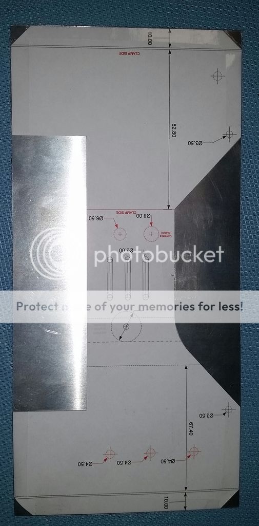
As previously mentioned I decided to have a go at making an aluminium bumper. I wanted it to be light so I decided to make a hollow bumper based off Steffan's plans. Using Visio I made up a template and started work.

Here are the side wallls based directly off the plans.

Image

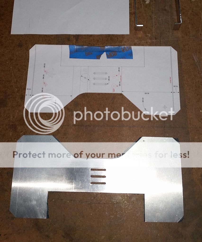
However, as I started working out the top plate I noted that the side wall plans don't line up correctly with the reference bumper photos on this site. Specifically, around the underside of the centre where the section tapers down. I ended up building the missing part back up with weld and progressed to make the top plate and centre wing walls.

Image

Image

I welded these parts up and filed/sanded the edges out.

Image

I made up the back plate in similar fashion to the top plate.

Image

Did a test fit of the back plate.
Image

Then weld on the back plate, welded up the ends and filed/sanded (and sanded some more) the edges back to finished the metal work.

Image

Image

Image

Image

Test fist against the pack shell.

Image

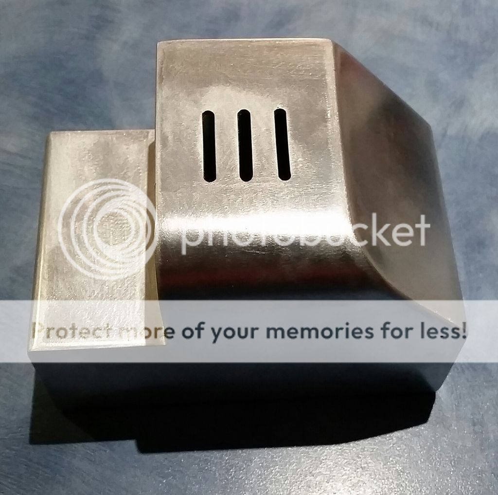
While not perfect, I'm quite happy with how it turned out given my developing welding skills. The next step with it will be to use some epoxy filler on the inside edges to create the taper along the fins. This will be tomorrow's task.

As a side note I found this to be the most difficult part to weld to date, but then again I think that I think that about each part somewhere along the line. Oh, and I'm still trying to find a good way to unclog aluminium from my files.

Anyway, I hope that you guys/gals found this update interesting. Until next time, bye.

Pete :cool:
#4850575
Stunning! Absolutely stunning!
#4850576
I'm not sure of the exact name of it, but I use a wire brush to clean out debris from my files. It looks like a coarse hairbrush almost. I got mine at Lowe's, I'm sure Home Depot would have it too.
#4850632
Hi guys.

Thanks for the supporting words, it helps me stay motivated to see this project through.

Ejgunth87, I have a file wire brush (the type with short bristtles) but it doesn't seem to be able to get the larger burs of aluminum out of the file. In fact, I broke the plastic handle off it yesterday by pushing down to hard trying to clean one of my more clogged files. I have even tried running a piece of brass plate along the file (in the direction of the teeth), and this works well on removing the burs for the flat files but not on the half round one. So the search is still on for another technique.

Pete :cool:
#4851122
Hi Guys/Gals

Thanks again for the kind words/ I only have a couple of days left of my Christmas leave so I thought that I would make a push on completing the various pack parts.

So I decided to complete the PPD and make the Ion Arm cap. I had previously cut the body of the PPD, and I wanted to make a hollow body one to help keep the weight down, so it was time to cap the ends off and get the epoxy out.

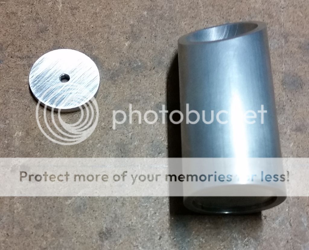
I machined down two caps that fit inside the tube's body, each was made to be a tight fit. This photo shows the bottom cap installed and the top drilled and tapped ready for installation.

Image

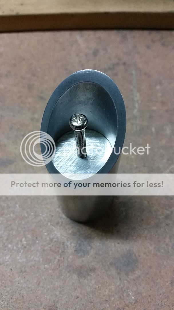
Top installed with the aid of a temporary screw to position it. This cap wasn't quite as tight as the bottom one, so I super glued it into pace read for the epoxy.
Image

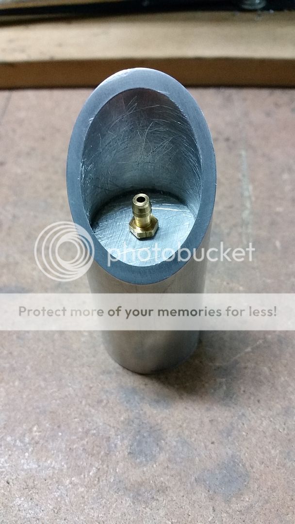
The next shot shows the barb temporarily installed that the tube will connect to. I have roughed up the inside faces so that he epoxy had something to better adhere to.

Image

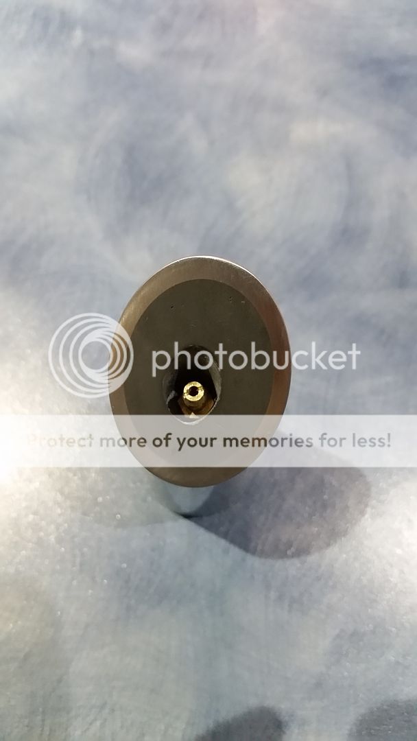
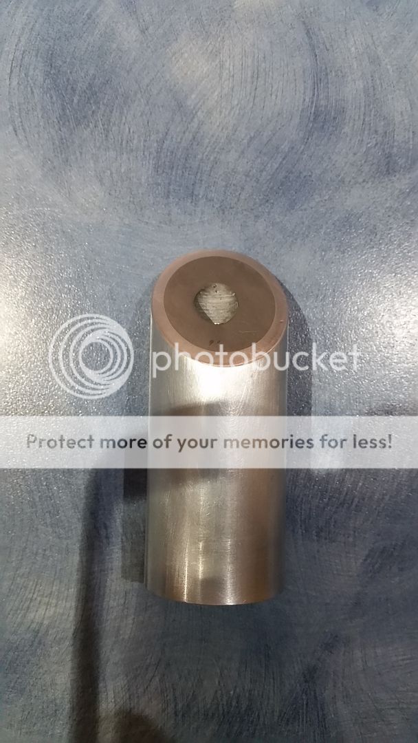
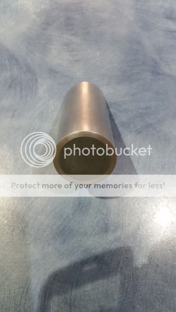
Ok, now this is where I forgot to take more progress photos, so here is the end result. I drilled the epoxy out to a diameter that allows the split loom to slide down over the barb. A couple of minor bubbles in the epoxy but not all that noticable in real life.

Image

Image

Image

Today, I had a great time building the Ion Arm cap with some assistance from my son. This is the first time that he has helped out on the build (not from a lack of me trying to get him involved) and it was great fun working together. He helped do the mark-outs, centre punching and a little bit of drilling and taping.
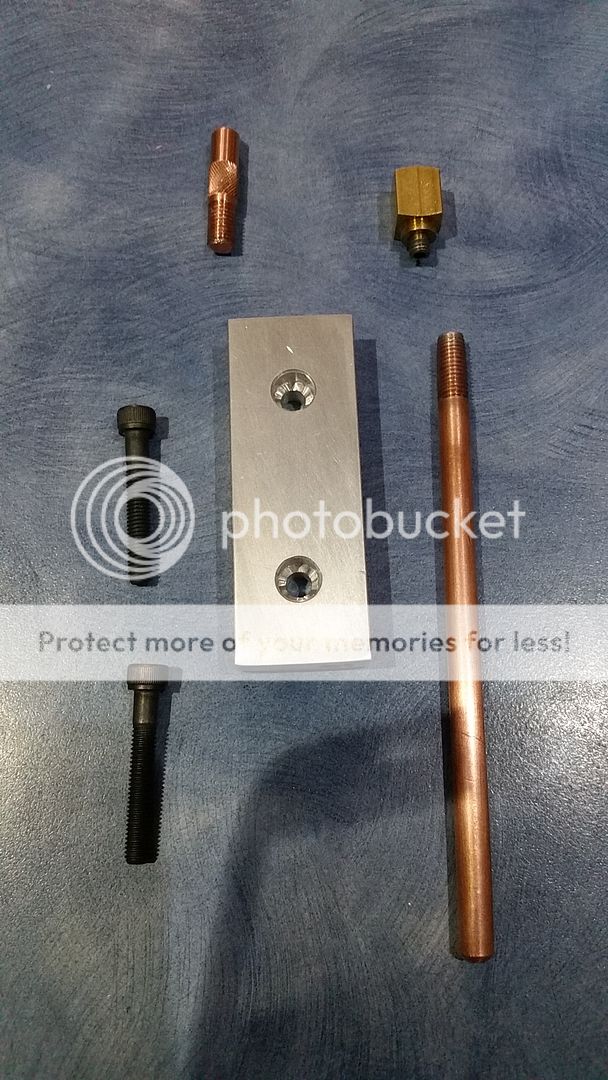
I made the cap body out of a solid piece of aluminium, and the rods out of copper. I made the rods threaded so that could be changed in the future if need be.

Again a bit tardy with progress photos, so here is the end result. Parts seperated.
Image

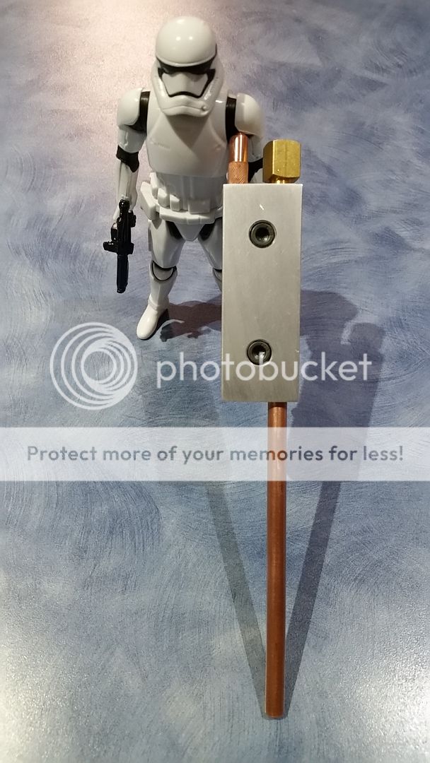
And I believe that "This is the droid .... ahum.... Ion Arm Cap that you are looking for."
Image

So this only leaves the Booster Frame to be built for the pack shell. I think that I read somewhere that there is a few new dimension discoveries for the Booster Frame since Stefan made his plans. So I will have to try and find these updates again before I start on it, and of course trying to figure out how I'm going to make up the hexagonal ladder rails, and the Masonite patterns. Hmm more obsessing to be done......

Cheers, Pete :cool:
Kingpin, OCP_Model-001 liked this
#4857606
Hi guys. It's been a while since my last post so here is a quick update.

It's been a long hit summer this year in Queensland, and I found myself fleeing the 35C days and 70-90% humidity indoors in air conditioning or in the pool most of the time. But i have managed to do a bit of work on the pack.

I decided to work on the booster frame, which I now know is a deceptively simple looking part. Keeping true to the rest of the build I went with aluminium fir this piece. I didn't have a piece of plate, so I laminated two 1/8" pieces together with JB Weld to make the base. Then I cut down a strip of stair tread to get the ridged wings. I hand stamped the masonite pattern on three small pieces that I glued on as the three rungs. And now fir the hard bit.... I couldn't find hexagonal aluminum bar with the same diameter of a pencil, so I made my own by cutting down a length of 1/2" square bar on the table saw. Let me tell you this is a challenge. But after a couple of goes I was happy enough with the result.

Photo time. First here is the hex aluminium bar I made.
Image

Image

Unfortunately I didn't take a lot of inbetween build photos so here it is nearing the end.
Image

Image

And here it is complete, less a couple of minor touch ups. Image

Image

I think that it came out ok, and looks about right when placed on the pack. I still need to put a slight half round on the back to sit up against the booster tube.

Anyway, that's it for tonight. Hopefully my next post will show a great deal more development.

Pete.
twmedford23, legend642 liked this
#4857868
Lovely work pete,don't blame you for hiding in the pool from those temps, couldn't stick that here. We are just coming out of our winter, not a cold one but very wet & miserable most days. Looking forward to more ;)

MT
#4857926
Thanks for the support guys.

I'm really keen to finish the pack section off and make a start on thrower.

This weekend I'm hoping to finish a couple of touch ups on the booster frame and make the motherboard. What's the concensus on the correct amount of overhang on the motherboard? Looking at photos it seems to vary. I was thinking about 1/16 inch even all around as an idealised fit. Happy to hear suggestions on this.

Pete
#4857945
This is literally proton pack porn!!!! Through each new pic and update I grinned harder and harder. This has got to be the most beautiful construction I have ever had the privilege of seeing. Huge respect to you, and more power to your elbow Sir - I really can't wait to see the whole finished project! I have seen other commenters say about not painting it, and you can see why, it's so beautiful in just the naked metal. The details and care on this are absolutely second to none, and if anyone asks you if you are a God... just show them the photos from this thread!!
( sniff... pauses to wipe away tears of humbled beauty, after a mild GB related religious experience)
OCP_Model-001 liked this
#4858016
Hi guys. Thanks for the generous comments, they really are helpful in maintaining motivation on this project.

Steve I think that is the best coment I ever recieved on anything, ever. I've still got a long way to go and heaps more to learn and ask along the way. I'll keep sharing the journey with you all.

I'm still undecided about mobo overhang though, flush or 1/16 inch idealised all the way around? Thoughts.

Pete
SteveGilmour liked this
#4860958
Hi fellow GB fans. Its been a while since my last post so its time for a fairly large update.

Last weekend I reached a bit of milestone for my build. I have now finished making and mounting all of the steel work on the main pack (bar the gun hook which I will make later as I currently don't have the right thickness aluminium plate.)

So lets get started with catchup photos.

I marked out and cut the motherboard out of 3mm thick aluminium sheet. I also made mounting brackets out of 1/8" thick, 1" x 2" angle which I JB welded an extra plate to(not shown in the photos unfortunately) for extra screw thread to hold the shell on. I pop riveted these to the MB using those wide head rivets.

Image

Image

The next task was to put the shell on a diet and remove some of the internal walls that were adding weight for no gain. Plus removing these walls has created pathways for the future cable runs inside the pack. I'm in two minds about showing inside photos, my early welding wasn't the best as I was starting out, plus you guys may just not be interested..hmm if there is enough interest I'll post a couple in the future.

Time to mount my Alice frame (Obtained from the GBFans store) to the pack using the hockey puck method. Ultimately I would like to change the Alice frame to a genuine 1980's one to be a bit more authentic with the build.
Now I must say that it quite difficult to find affordable hockey pucks locally in Brisbane, so I had to resort to EBay. I ended up buying three thinking that I would have a couple of spare if I stuff the half moon cut up, ultimately I ended up using all three in a PssdffJay style mounting arrangement. Now I must fess up that I'm a 41 year old that has never before held a hockey puck, so it was amusing to play with them for a while before getting down to business.
So the next photos shows tings that probably would get you arrested in Canada.

To cut the pucks I made a sacrificial holding board that I could securely mount on my miter saw, and keep my fingers safe.
Image

I was surprised how easily the saw cut the rubber. But I took it nice and slow just to be careful of the saw blade jamming up.

Image

Now for the bottom mounts. Make the first cut then spin the puck around for the second, using gaffer tape and wood blocks to hold things down safely.
Image

Alice frame sat in place.
Image

Now unfortunately I got so tied up with the build I forgot to take photos, well except for a boring photo of the ribbon clamp build. (Not sure why I took this one and forgot to take more.)
Image

Anyway, after much part positioning, measuring, changing my mind, repositioning, studying photos of the real packs, etc, etc I have arrived at this.

Image

Image

Image

Image

Image

Image

Not all of the small fittings are on in the above photos, and some holes are yet to be drilled out and tapped for these.
I'm fairly happy with how it turned out, not perfect but much better than I thought it would be when I started. I have a minor amount of putty filling to do under the forward edge of the HGA and Booster tube base (near the PPD) where the aluminum pulled in a bit from the welds (or was eroded away from excessive sanding ;), but nothing more than a mm in a couple of places. My biggest error so far is one from the start when I welded up the EDA, I spent to long welding the EDA to the gearbox and caused an internal wall to sag, which ultimately had the effect that the bottom of the EDA slopes inwardly from the top to the motherboard. Hopefully with the ribbon cable on and other parts and painted black it wont be too noticeable. Plus I did the calcs, and worked out that the pack will be safe to use so long as I don't cross the streams! :sigh:

So that's it, time to start on the thrower build. All comments, criticism welcome as always.

Cheers,

Pete. :cool:
#4861015
Lovely work P, don't worry about the inside, you should see mine! Your pack inside is probably better finished than my shell outside lols :) I have support walls left that I really should have removed before i put it all together. Looking forward to your thrower, will be a good one I'm sure ;)
#4861306
So beautiful!!

What's the final weight that this thing comes in at? just curious as to how much it differs from a standard resin shell with a combo of resin aluminum part like mine that ends up at about 25lbs with all the electronics.
#4861346
Hi there.

Thanks for the nice feedback everyone. At the moment it weighs 8.8kg (19.4pounds). I'm not sure what the thrower will with and the weight that the electronics will add, but I suspect that the all alloy build will be few kilos heavier. Does anyone know the weight of a completed thrower?

There is a minor amount more weight reduction that I could do to the shell, but not all that much. Actually in the future I plan on redoing the injectors because at the moment they are 1/8 thick wall tubes that is weight fir no real gain. Is just that I couldn't get thin wall locally.

Cheers

Pete.
#4864077
Hi all. Time for a small update.

Another familiar shape emerges from a flat sheet of aluminum.
Image

Image

Image

I'm hoping I don't stuff this up when I weld on the rear handle and front barrel attaching collar. It took a fair bit of sanding to get this far. ....

Also I need some ideas on grips. What do people recommend? I was contemplating carving a set out of wood and stain them so they look like the stock of a shotgun in color, but I'm not sure how this will look and how much work it will take.

P.
legend642, VBGBFan2005 liked this

This is awesome, One time. I love reading explanat[…]

And, lastly, for now, the video that prompted me t[…]

At some point, probably just better off opening up[…]

Spengler/84 wand Gun Track

So...I had more than a little problem with dis[…]