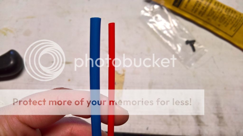
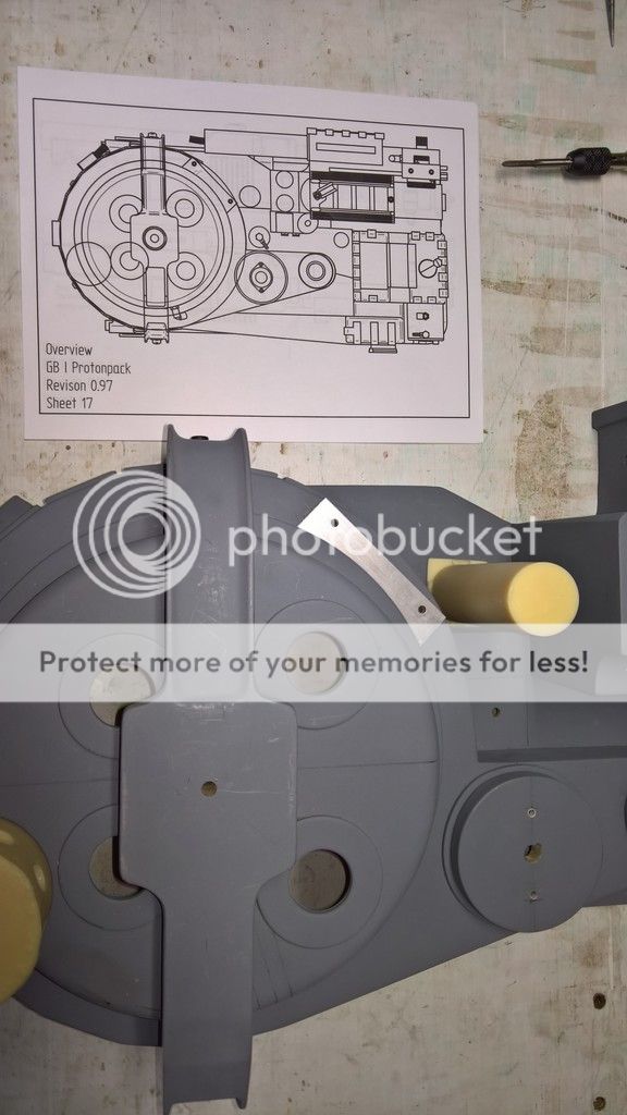
Cutting the mouse hole The “mouse hole” refers to the hole in the bottom right of the cyclotron for the loom that eventually connects to the neutrino wand.
Although the interior diameter of the loom measures ¾” inches, I measured the diameter of the exterior to be 1” wide. I then found a socket that was 1” wide as well. After finding the centre of the appropriate shell plate and marking a ½” distance on each side of the centre, I traced the circumference of the socket to mark the 1” mouse hole.

Then I drilled the hole using a 1” hole saw:

I noticed some builders removed the two pointy lips from the shell on the bottom portion of the mouse hole. I imagine they did this because they were worried that the lips might accidentally puncture or cut the loom. If I kept the lips, should I be worried about this?
Fitting the booster cap into the booster tube I was curious as to how one accomplishes this task without drilling any screws from the outside of the booster tube. So, naturally, I asked Ben through Facebook Messenger. Within a couple of minutes, he explained everything to me.
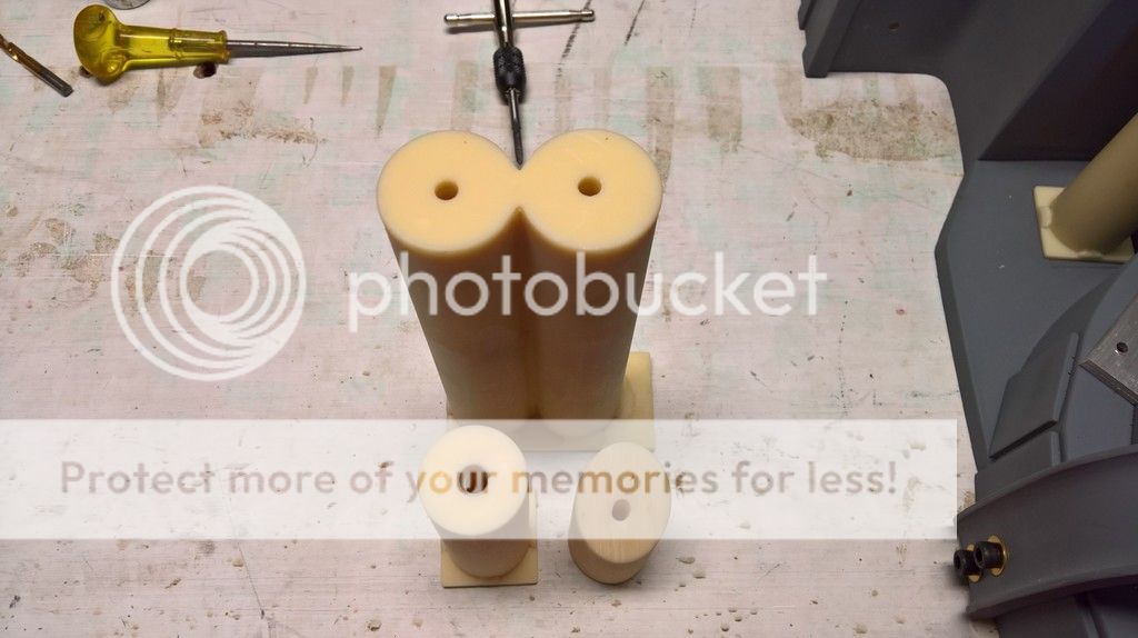
Firstly, Ben cuts and sands a 1” square piece of wood until it fits snuggly inside the tube. Secondly, he pushes the resin booster cap into the tube to set the square piece of wood to the proper height in the tube. Thirdly, he removes the booster cap and then places a load of hot glue on top of the piece of wood. Fourthly, he reinserts the booster cap down the booster tube and presses it against the piece of wood. The glue gushes out between the grips and the tube, thus securing the booster cap into the booster tube.
My dad and I found a piece of wood lying around in the garage and cut it to the proper width. We rounded the edges with a hand planer. Although Ben’s instructions specified a 1” long piece of wood, we ended up creating one that was 2” long for the simple reason that we saw no harm in doing so.

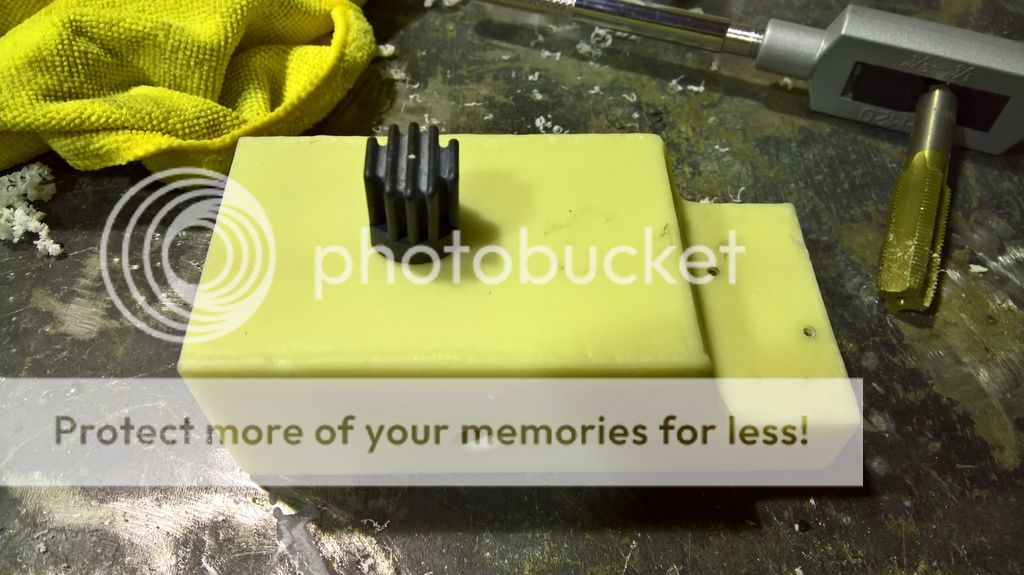
Then I fit the piece of wood down the booster tube, like so:

Finally, I placed the resin booster cap into the cap and set the height of the piece of wood according to measurements in Stefan’s plans. The end of the resin booster cap is now protruding outside of the booster tube by ¼”.

Although I could have poured the glue onto the piece of wood and properly secured booster cap into the tube, I decided to finish this part another day. I intend to sand down the piece of wood a little bit and paint the booster cap before permanently gluing it into place.
Ribbon cable hole This is another hole where I could not find any specifications in Stefan’s plans, so like most of the builders here, I decided to make a best guess. PssdffJay and Venkman's Swagger both drilled a ¾” hole in their shells, so if that worked for them, well that was good enough for me. Once again, I used a socket to trace the circumference of the ¾” hole. Using a ¼” drill bit, I ensured that the socket was a uniform distance from both edges of the shell, like so:

Then I drilled a nice and clean hole with a ¾” hole saw:
 Crank generator hole for the vacuum line loom*ADVISORY: the following update contains mature subject mature, including scenes of brutality and violence. Viewer discretion is advised.*
 Seriously, this isn’t for the faint of heart. This is my first major screw up on this pack build. One that caused damage and needs fixing.
Although many shells seem to have a hollow crank generator, it’s only partially hollow in the Benofkent Props shell. Drilling the hole for the loom of the vacuum line isn’t merely drilling a hole through the shell. It’s more akin to drill a shaft through the polyurethane.
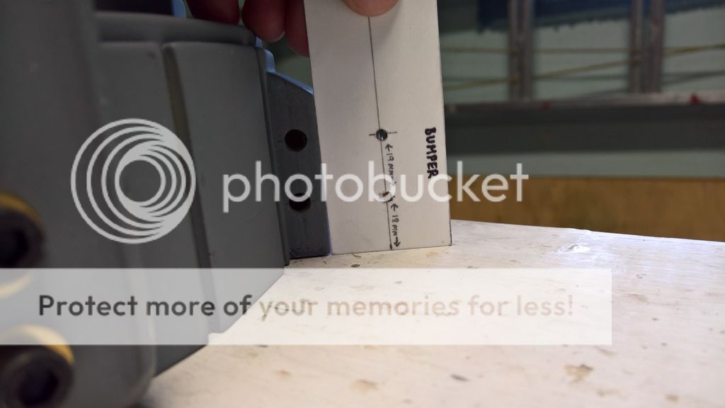
Using the same 1” socket trick, I traced the location of the hole on the crank generator:

Then I marked the centre of the hole onto the shell and I started drilling a little pilot hole. Immediately I found that it was difficult to drill straight, since part of the shell was obstructing the drill. This only meant that my drilling was going into have a slight downward angle.
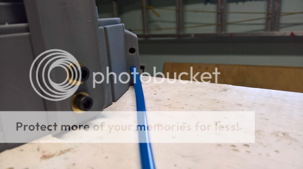
Then I switched my drill bit for 7/8” hole saw. I chose 7/8” because I was worried that the 1” hole saw would be too large and that the hole would be two close to the extremities of the shell. After testing on a piece of wood, I found that the loom still fit within a 7/8” hole, even though it was really tight.
Remember when I said that the crank generator is partially hollow? Well, as soon as the hole saw found the hollow part of the shell, it really pulled toward that direction. This is what happened:

GROSS. Chipping occured, but since this part would be covered by the loom (and a ¾” wood dowling that I plan to fit inside the loom to straighten it), I figured it wasn’t a big deal.
So I decided to proceed continue my drilling using a Dremel, both
through the hole that I had just drilled and from the inside of the shell.
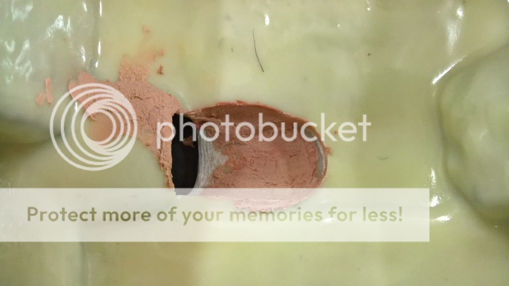
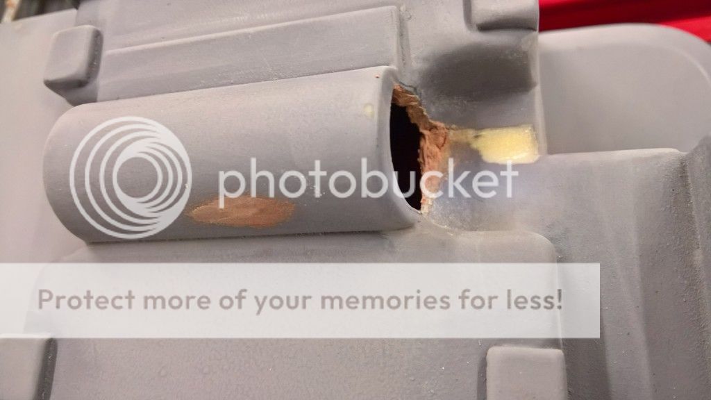
The Dremel was working really well until this happened:

You see that little black line on the bottom? Well, here’s a view from the outside:

After two screw-ups, I decided I had enough. I probably grinded out a large enough shaft for the dowling and loom anyhow.
Although the damage is certainly disheartening, I will try to patch it up with some epoxy or some Bondo. Not today, though.
Wish me luck!
Dale PH-25 resistor (no ring variant) The arrival by mail of a Dale PH-25 resistor really picked me up after the infamous
Crank Generator Massacre. I had purchased it from Dreamstalker, who was kind enough to reply to my wanted ad on the GBFans forum. Thanks again, Isabel!
Well, the PH-25 is
almost a Dale… it’s labelled as a
Dalohm PH-25-25W 76 ohm 3% 016. It’s metal and it feels like the real deal. Close enough.

Now that I have this part, I can drill (and tap) the last remaining hole for the ion arm. That, too, will be for another day.


 GB1 and GB 2 Uniform Build Thread:
  - By GhostFaceX
 - By Kingpin
 - By timeware