Mounting the ion arm to the shell I referred to this step earlier in my build thread, just prior to painting the shell, resin and aluminum components. As you read further into this update, I think you will understand why I chose to paint these parts prior to mounting the ion arm and the booster tube.
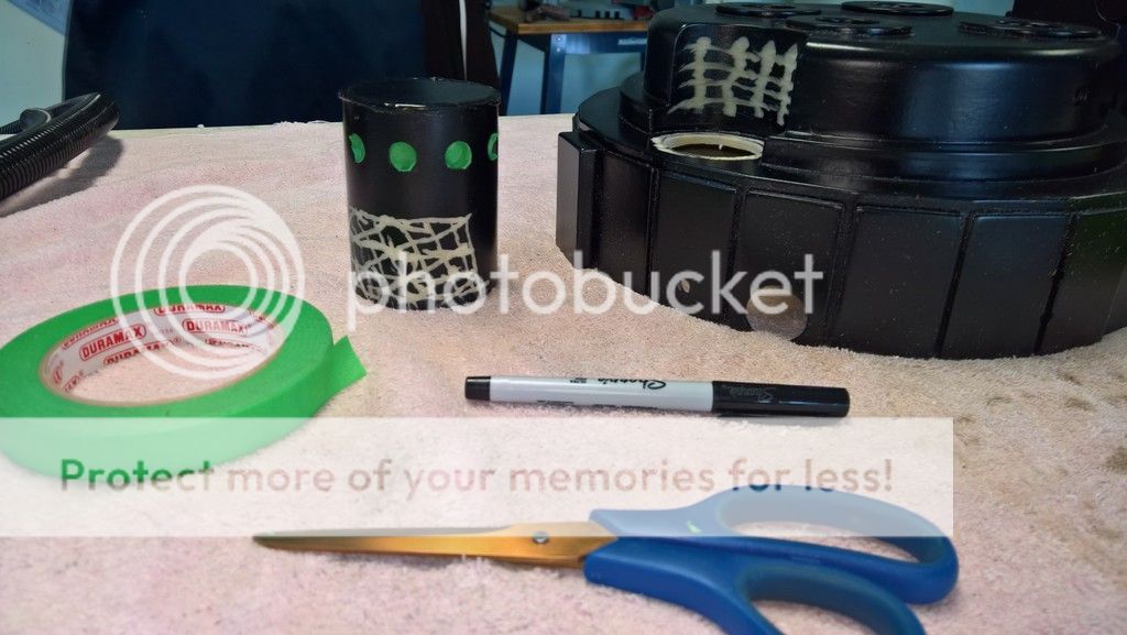
Some people use tape or clamps to hold their components before drilling holes and securing everything with screws. I use Bondo.
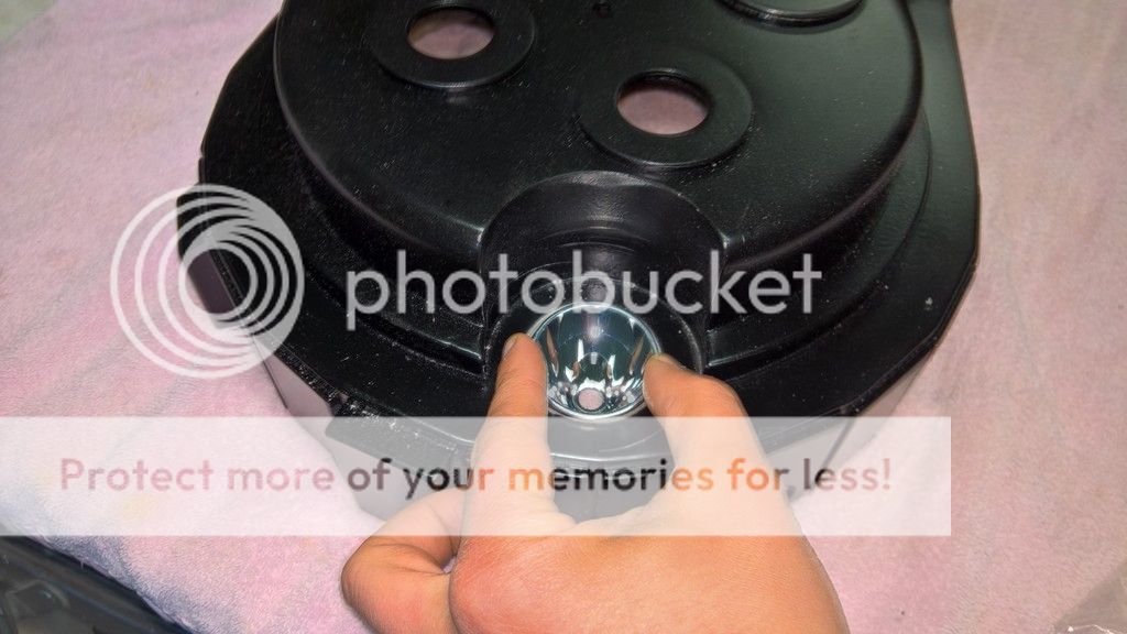
The first step involved tracing the base of the ion arm onto the shell using a Sharpie pen. Using a Dremel, I then sanded some grooves into the polyurethane of the shell within the lines that I had just traced. I also sanded similar grooves into the resin at the base of the ion arm, like so:
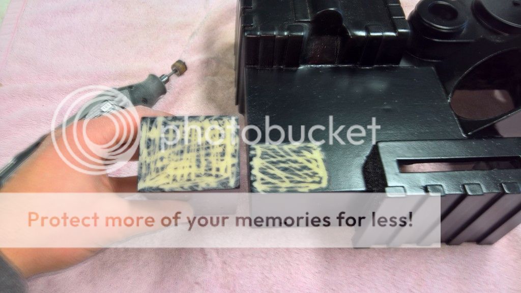
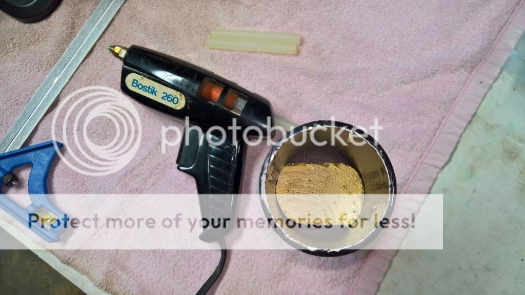
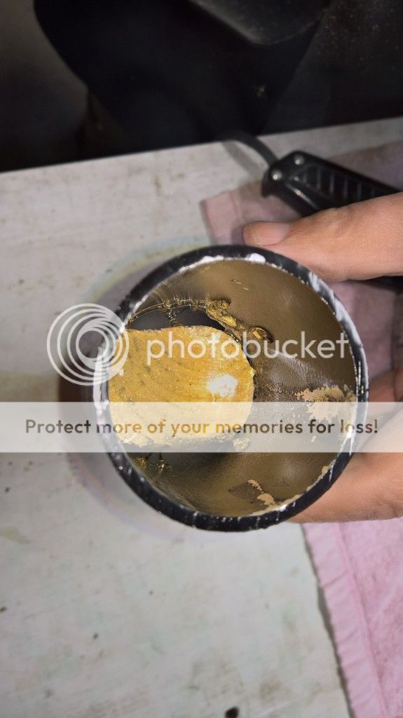
I prepared a little bit of Bondo to spread thinly over both the shell and the base of the ion arm.
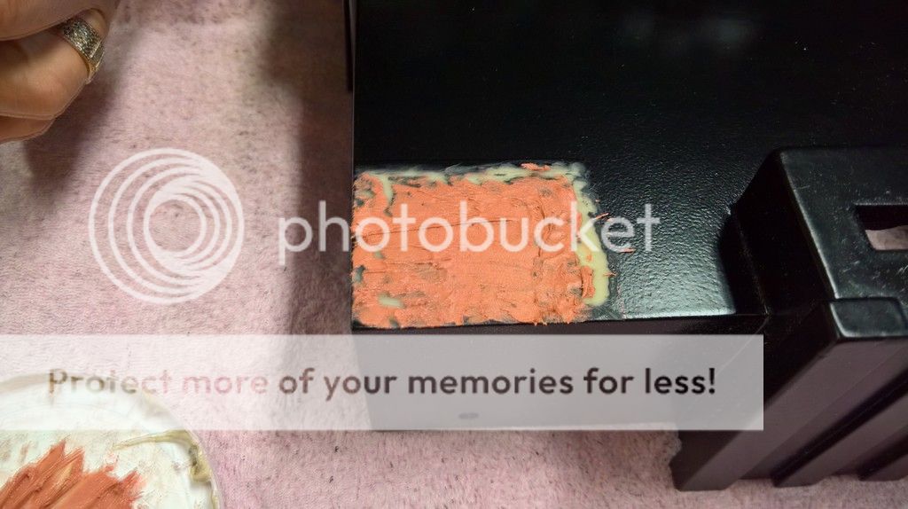
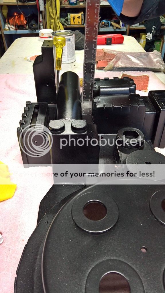
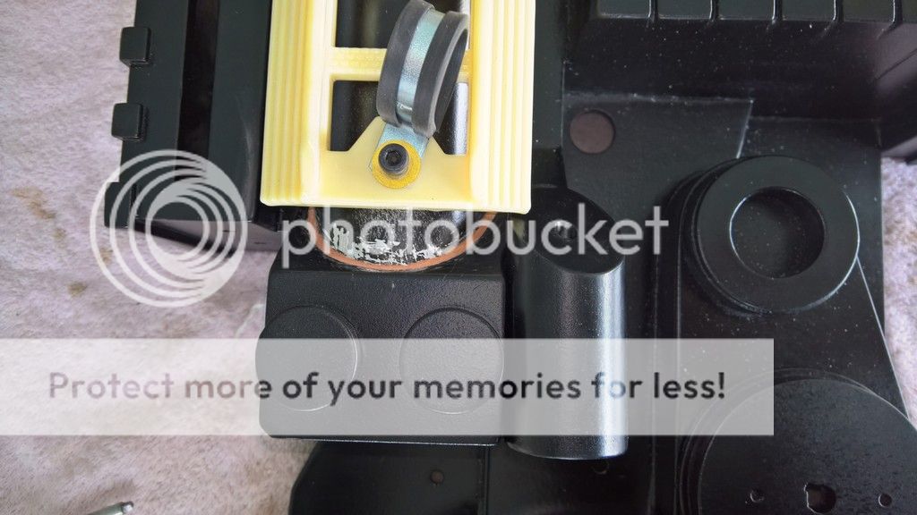
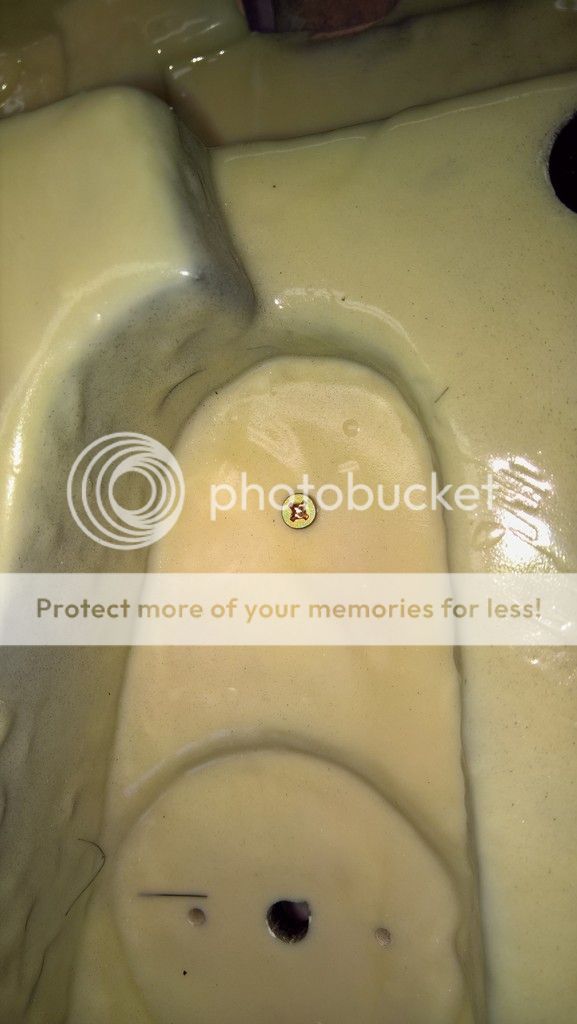
I placed the ion arm onto the shell, pressing firmly downward so that the Bondo would spread into the sanded grooves. Using a set square, I lined up the ion arm perfectly with the edges of the shell.
Lesson learned: remember to wipe your fingers with a cloth or a rag as you are applying Bondo and manipulating your pack parts. You can see in the picture that I didn’t, so my fingers left little traces of Bondo on the ion arm. As the Bondo hardens and you try to remove these traces, it’s easy to chip the resin or the paint. The best bet is to let the traces of Bondo dry, then sand them off later.
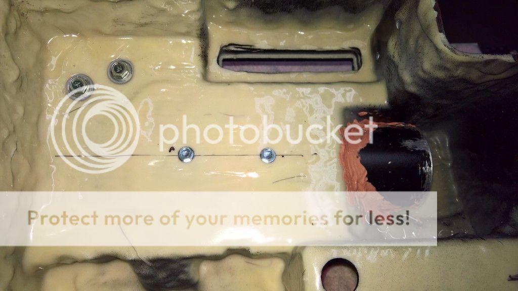
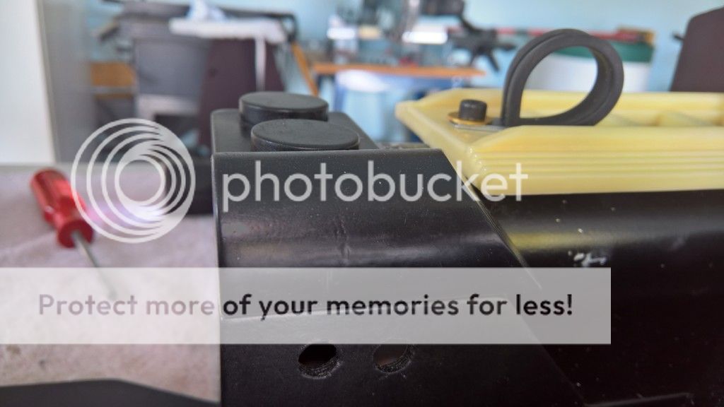
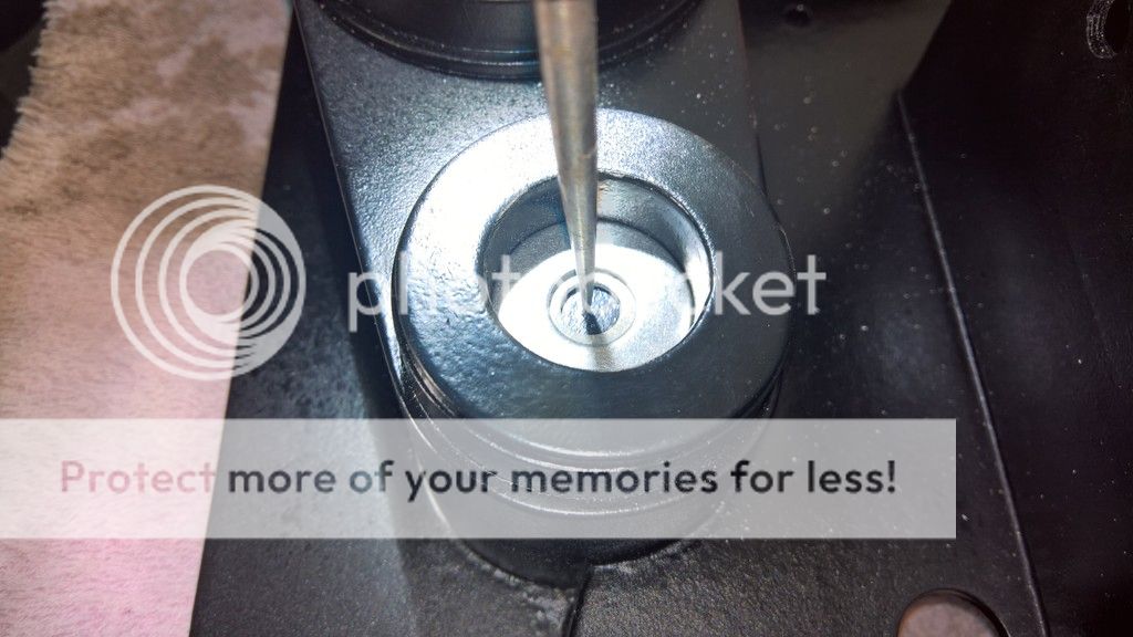
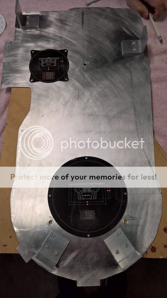
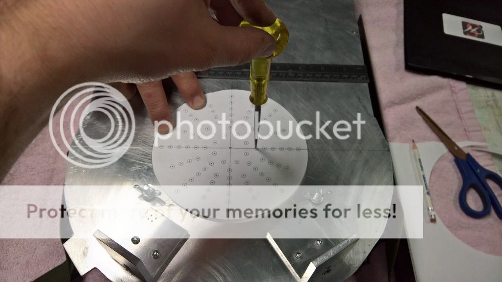
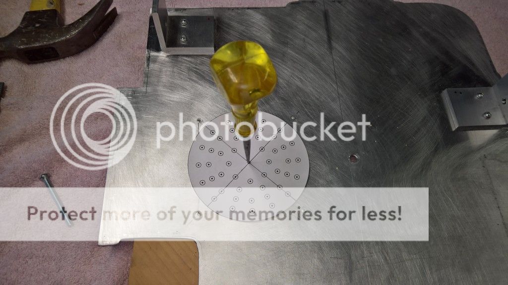
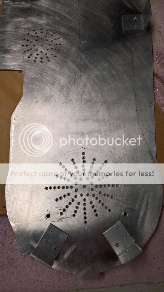
After the Bondo had cured, it was time to flip the shell over and drill some 7/32” holes for the two 3/16” x 3” self-drilling roofing screws (with rubber washers) that would firmly secure the ion arm to the shell. These are the same screws that are used to secure the injector tubes, the beam line and the filler plug to the shell.
Since these screws are three inches long, I had to be careful to place the holes in positions that would not go through the holes I had drilled for the PH-25 resistor and the Legris (or in this case SMC) elbow. Hence the somewhat diagonal positioning seen here:
 Mounting the booster tube to the shell
 Essentially, I mounted the booster tube in a similar method than the ion arm.
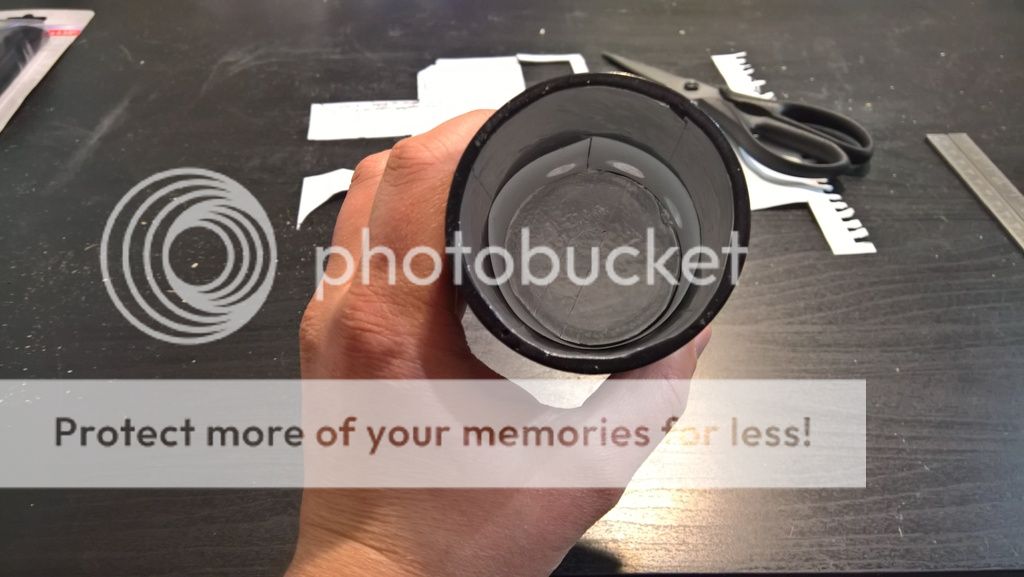
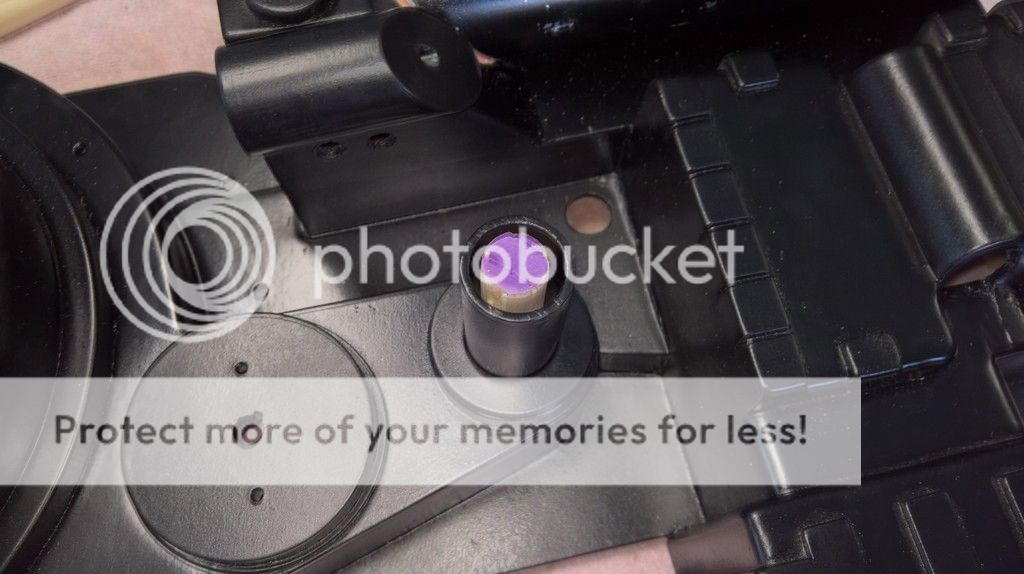
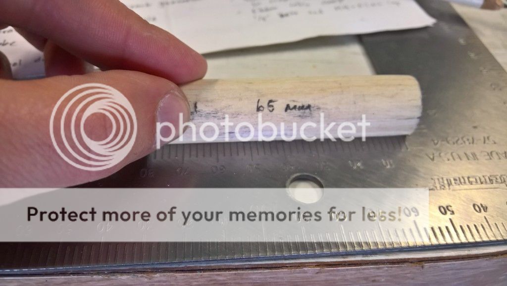
I am very fortunate that Benofkent Props pre-cuts a hole into their shells for the aluminum booster tube. The booster tube already fit into the hole in a tight and snug manner.
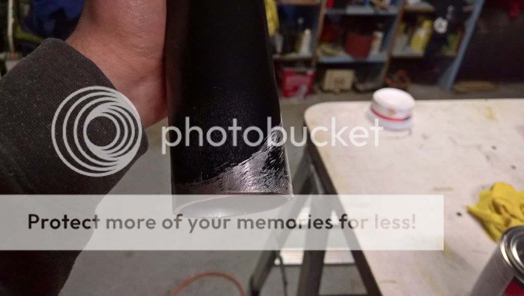
After placing the booster tube into its hole, I used my Sharpie pen to mark the outline of the shell onto the booster tube. I also left a straight reference mark on the centre of the tube and onto the shell, so that I could easily line them up later when I needed to.
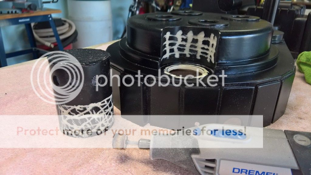
Using some coarse grit sand paper, I then sanded the booster tube underneath the shell outline that I had just traced moments ago with my Sharpie pen. I also sanded around the extremities of the shell hole.
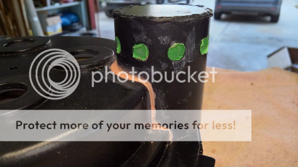
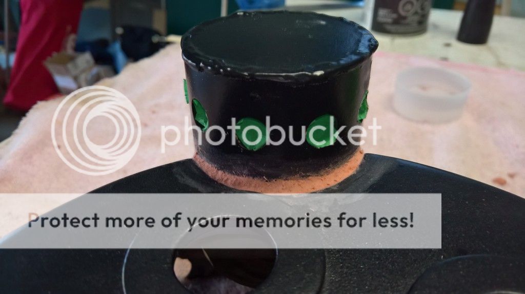
I then prepared some Bondo and spread it on the sanded areas of the booster tube, the lips of the shell hole and generously within the shell hole.
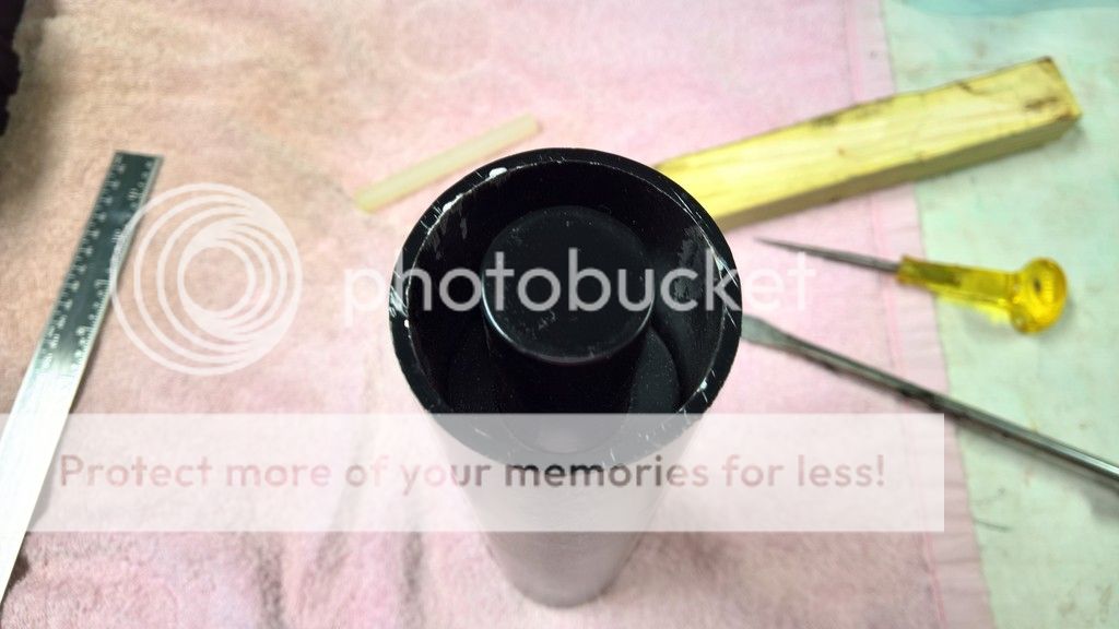
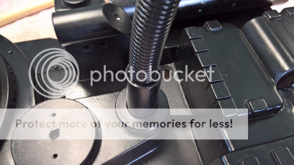
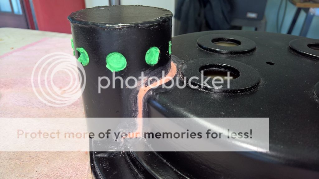
Once I placed the booster tube into the shell hole, I aligned the centre reference marks that I had made on the booster tube and the shell. I also set the booster tube to a distance of exactly one inch from the crank generator. Luckily, the metal ruler in my sliding T-square is exactly one-inch in width, so it was easy to line up the booster tube one ruler-width from the wall of the crank generator (at different points along the wall, of course). I also used my pilot hole punch between the ion arm and the booster tube to help hold the desired position as the bondo began to cure.
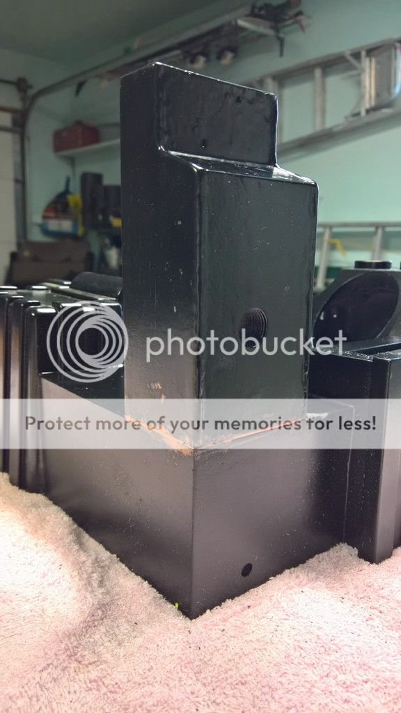
I then used my fingers to wipe away the excess Bondo. I tried to create the smooth look of a high pressure weld. What do you guys think?
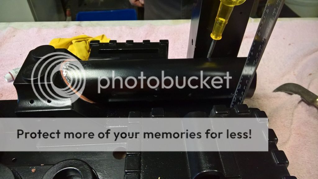
After the Bondo had cured, I flipped the shell around and grabbed my Sharpie pen. After measuring and calculating the centre of the booster tube, I traced a reference line up the inside of the shell. This line represents the length of the booster tube along its centre on the flip side of the shell.
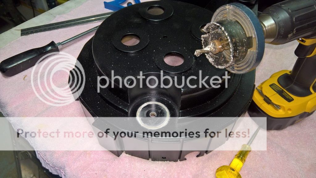
My objective here was to drill two holes through the shell and though one side of the aluminum booster tube. The holes are meant for the two mounting screws. Since I had so many of them on hand, I decided to use the same 10 x ¾” self-drilling screws that I used to mount the PPD to the shell (these screws were not listed in my first post and unfortunately am I no longer able to edit it to update my screws and bolts list), even if they have much larger threads than ridged cap-style bolt. I used a 9//64” drill bit for the pilot holes.
How did I measure the location of the screw holes?
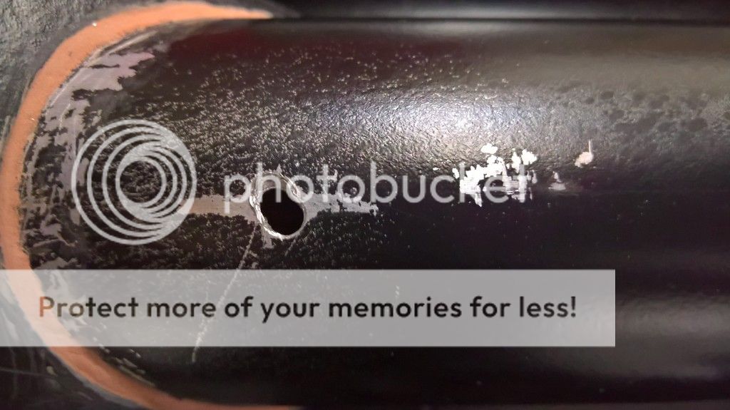
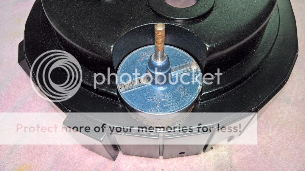
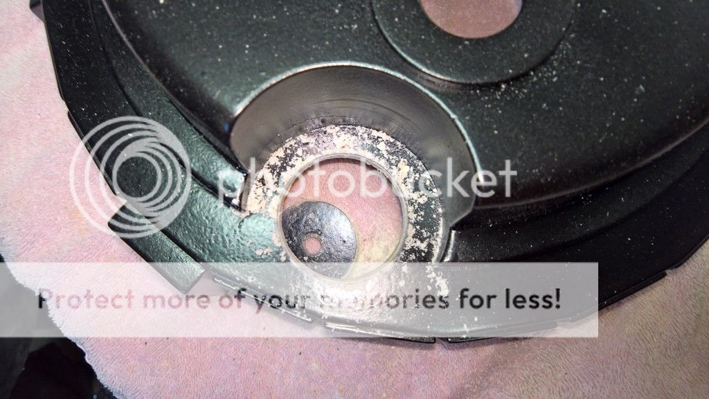
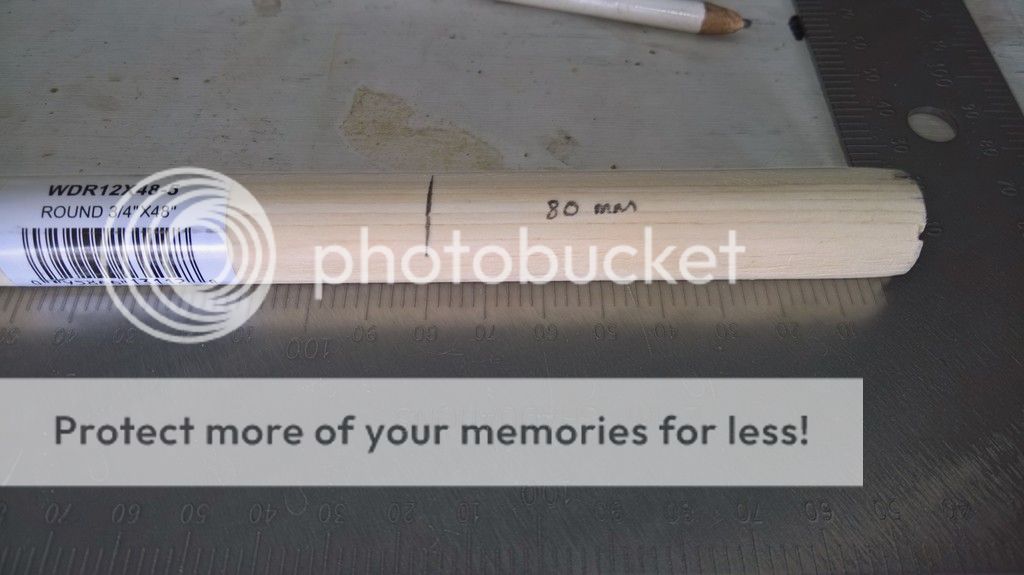
For the first screw, I wanted it to go into the wooden block inside the booster tube that is supporting the booster tube cap. I thought this would be an easy and efficient way to properly secure both the wooden block and the booster tube end cap inside the booster tube (in addition to the hot glue). To do this, I used the thin end of my digital caliper to measure depth of the booster tube cap inside the tube. Since the height of the base of the cap was about an inch, and since the wooden block below it is two inches long, it was easy to approximate its location along the refence line I had just drawn. Sure enough, as I drilled the first hole on the left, the drill bit brought up some wood dust.
For the second hole, I eyeballed its location to be along my reference line, but somewhere between the first screw and the ledge of the shell (where the booster tube is inserted).
One this was complete, this is one booster tube that isn’t going anywhere.
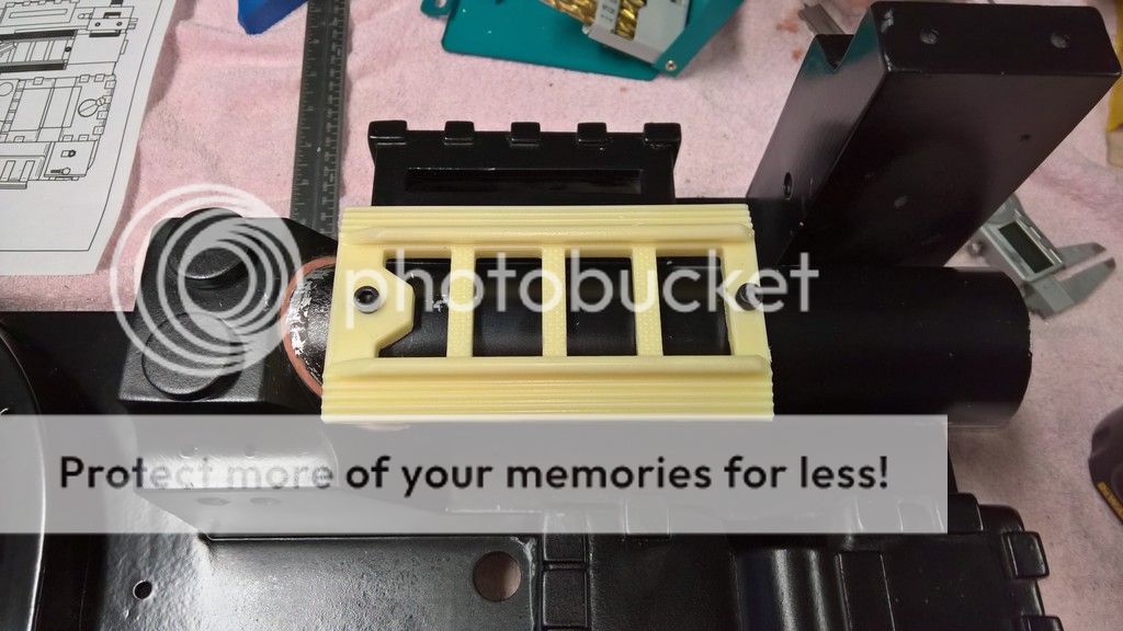
Mounting the booster tube ladder Unfortunately, I don’t have too many pictures for this step.
Using my digital caliper and my Sharpie pen, I measured and traced a line from one end of the booster tube to the other.
Using Stefan’s plans as a reference, I knew that the bottom edge of the ladder lined up with the bottom edge of the powercell box (on the shell) and the upper edge of the PPD cut-out (once again, on the shell).
Using my sliding T-square as a set square, I lined up the bottom of the ladder against the lines of the shell (as per the visual references in Stefan’s plans). I also positioned the ladder so that I could see my Sharpie pen line run through the middle of the bolt holes. Then I marked the bolt hole locations onto the booster tube using my pilot hole punch.
Then I took off the ladder and grabbed my drill. I used a 5/32” bit to drill both holes and I tapped them to M5 x 0.8 mm. The bolts I used are both M5 30 mm black ridged cap-style bolts.
While I think the methodology in drilling these two holes was sound, I made a minor mistake when drilling the first (bottom) hole. Although I had marked the location of the hole with my hole punch, I lined-up my drill bit with another mark which was probably left accidentally. In result, the hole was slightly to the right of the centre line. Since I am a perfectionist, I was pretty bummed about this mistake.
In the end, I tried drilling a hole exactly where it should have been, even though the holes would overlap. This ended up working well, since the hole (and thread) was still enough for the bolt to catch in the correct hole.
Furthermore, when the ladder is bolted onto the booster tube, no one can notice my mistake.
On the positive side, I had the unexpected benefit of having the top bolt screw into the wooden block inside the booster tube. This means there is a second bolt/screw holding the wooden block securely in place.


 GB1 and GB 2 Uniform Build Thread:
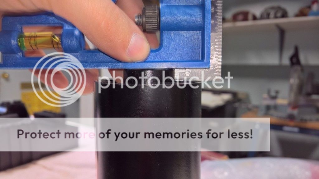


 - By Alphagaia
 - By tommyb345
 - By mrmichaelt