By Hijacker
#4829668
So, Alex, Phil, and I decided to collaborate and build a set of GB1 traps for ourselves. I've converted Stefan's plans to AutoCAD and changed the dimensions to fractional. I'll be cutting the bodies from 1/4" and 1/8" ABS. I'll also make the CAD files publicily available once I finish a few tweaks.

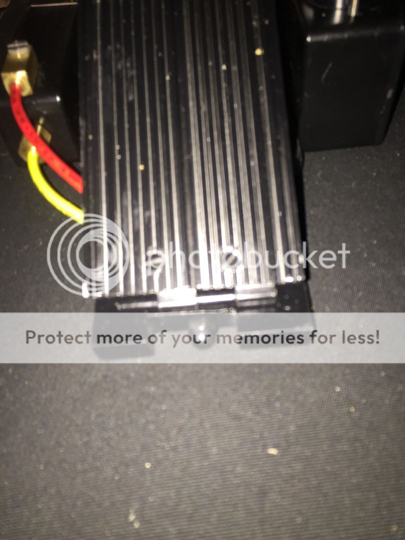
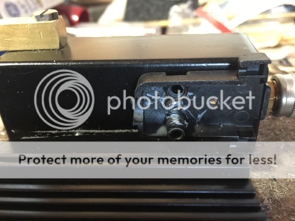
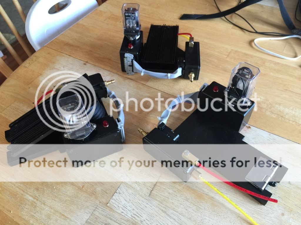
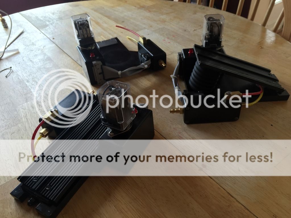
While I've been shopping options to cut the bodies, I've been amassing the greeblies. So far I have about 95% of the greeblies bought

Image
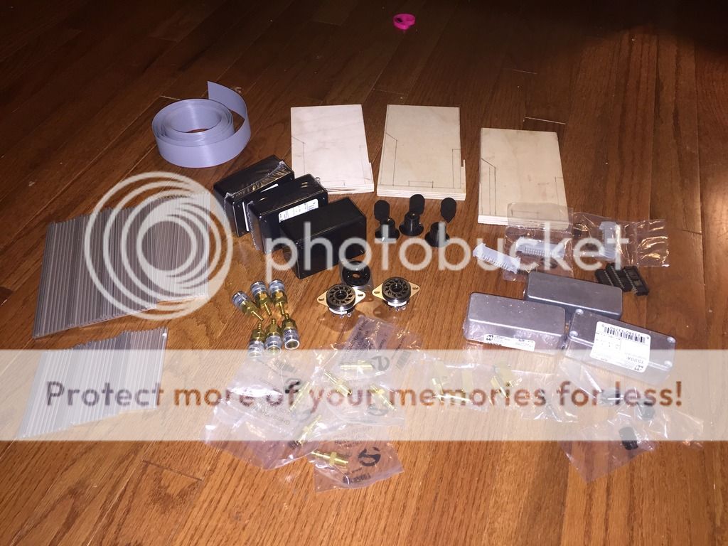
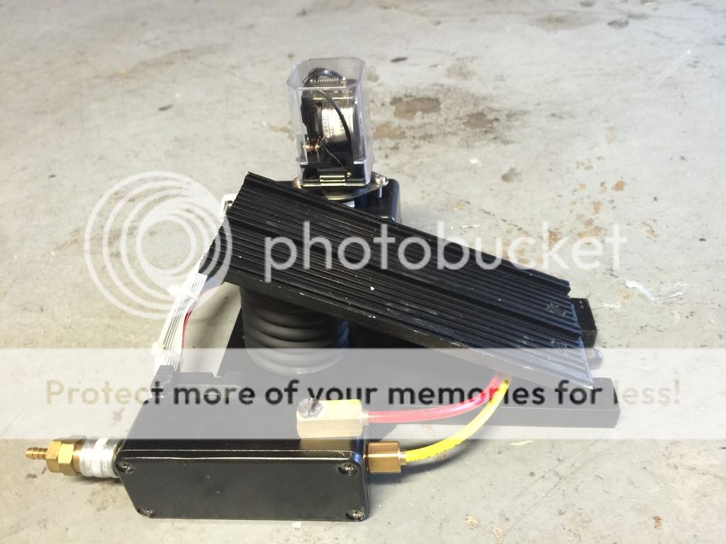
-The money shot. I torgot to grab my bellows material for this shot.

Image
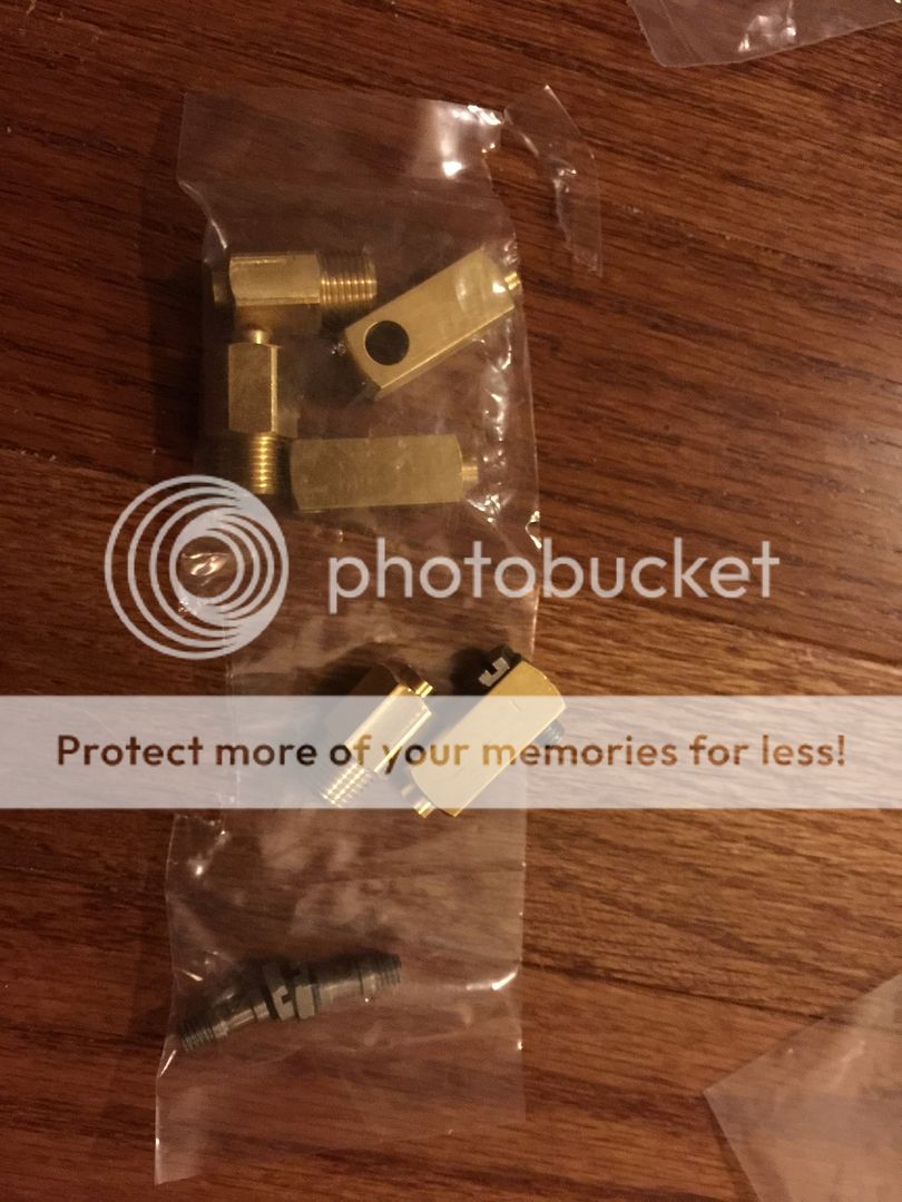
-AJ's amazing Legris reps. I am in absolute awe of them.
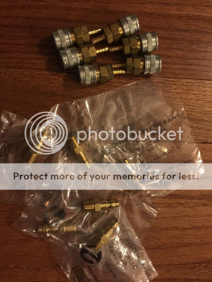

Image
-all the fosters!

Image
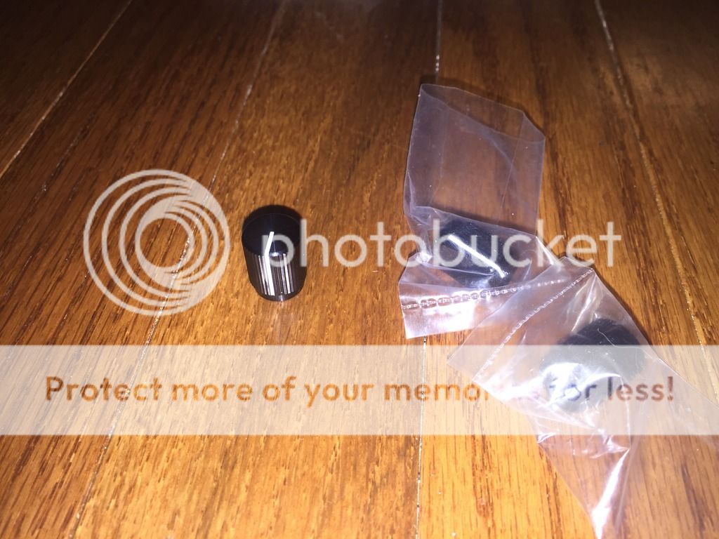
-Researching front knobs have made me go cross eyed. I've decided to take these and paint them to match the screen used. I have some silver knobs lined up and need to source the fader knobs.
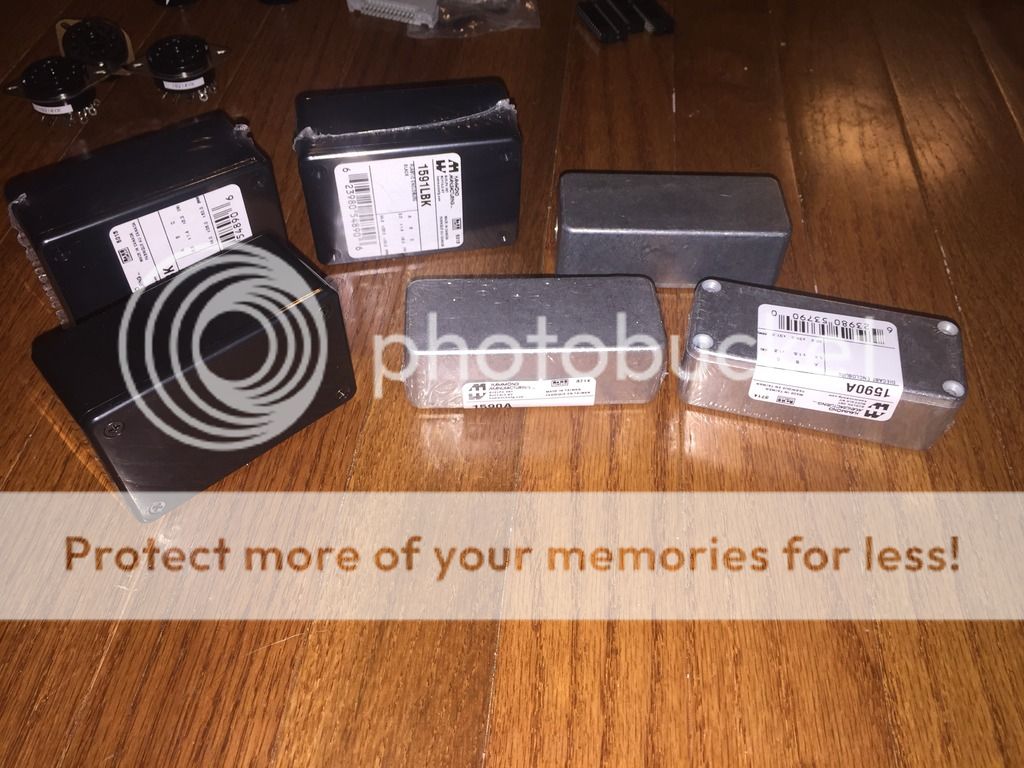
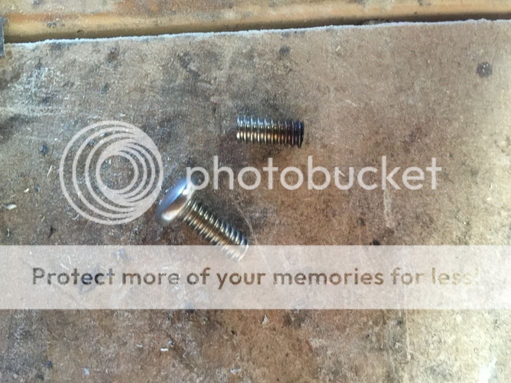
Image
-Just some boxes.

Image
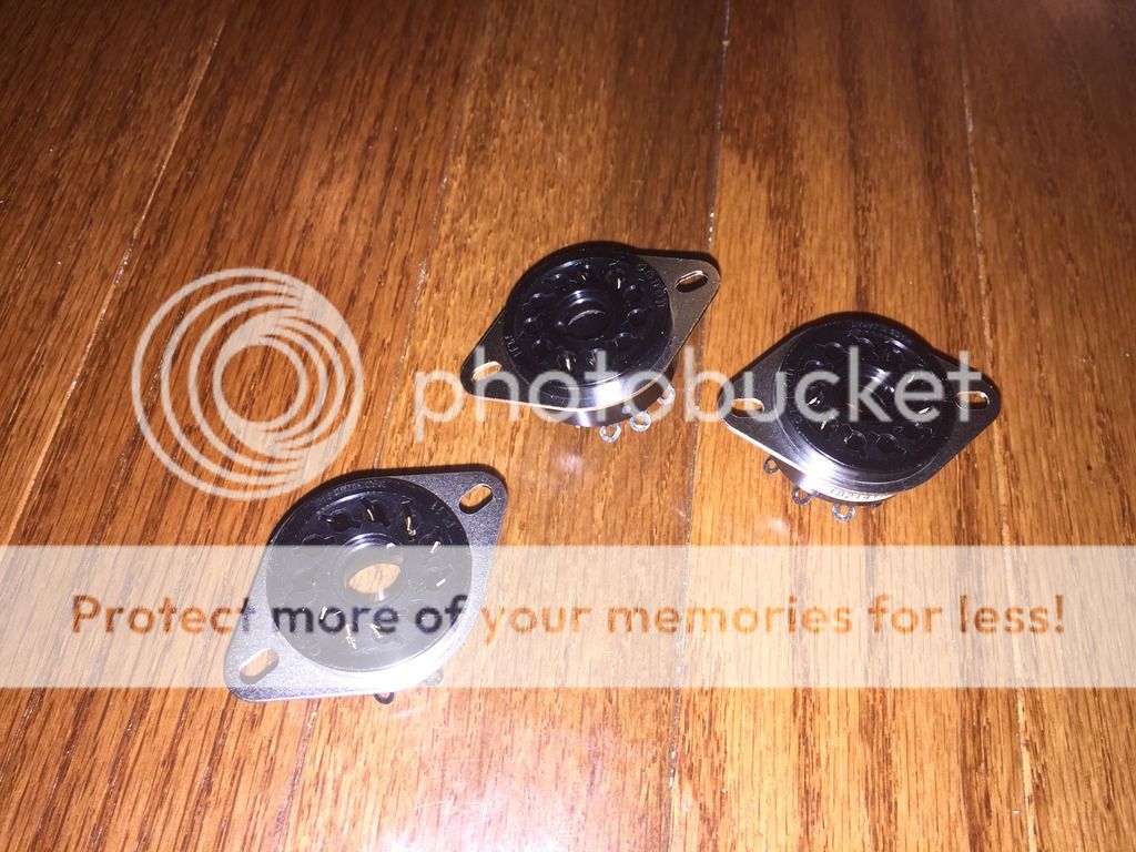
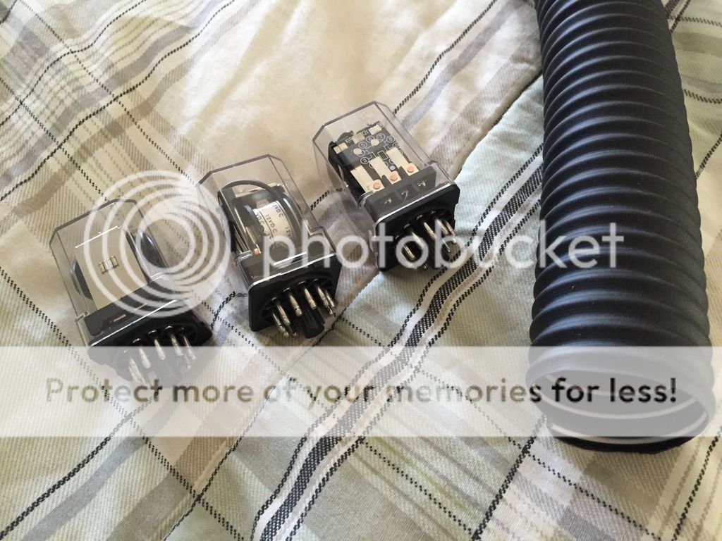
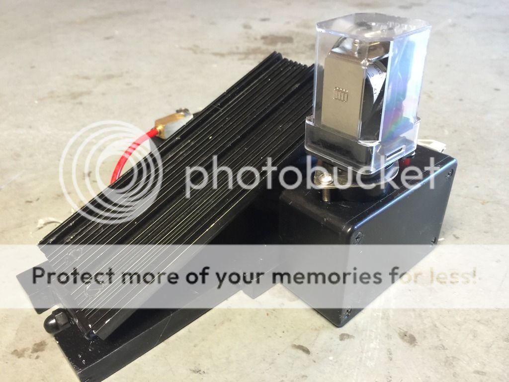
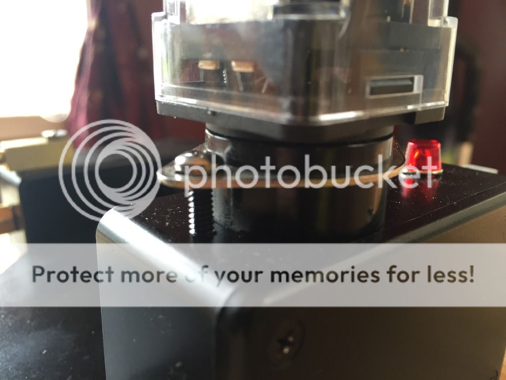
-Proper 11pin sockets. The ITT relay was nigh impossible to source. The only vendor that had stock quoted me at $85/piece. Yikes! I have close enoughs on the way.

Image
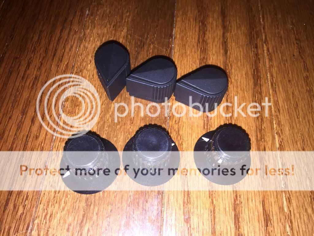
-EHC mil-spec knobs. The skirted dials are some random cheapoes I found just to cut 'em up.

Image
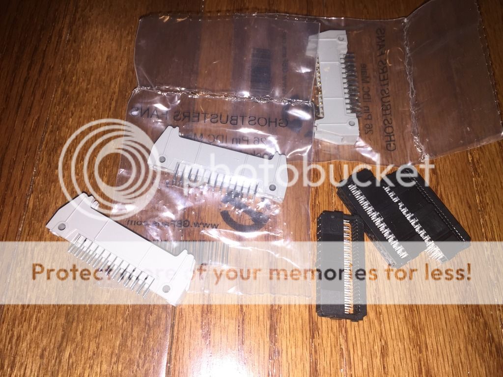
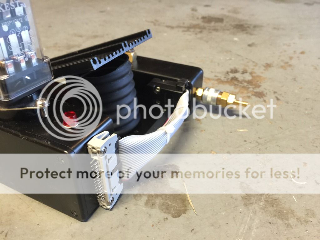
-26 pin IDC and header from 3M. The Ribbon cable is in the big pic. It's standard 26 pin grey with a red trace.

Image
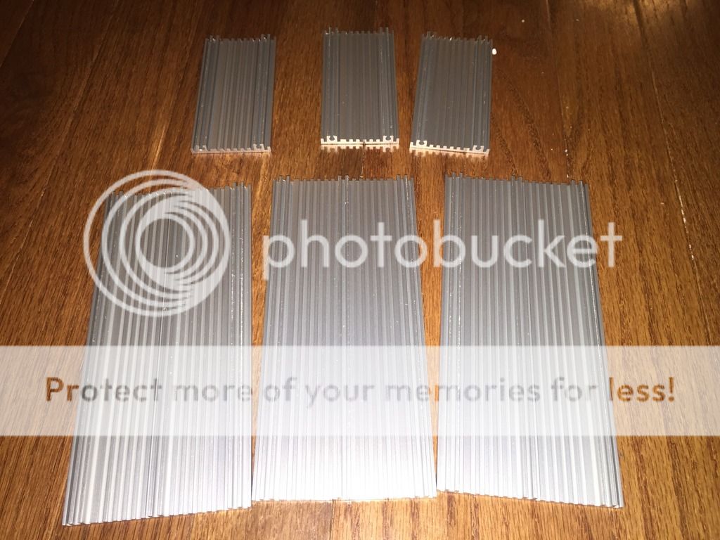
-Vector plates from the GB fans shop. I'm still debating if the 6.5" plate needs to have the outer fins cut off, or if that was a GB2 thing.

Image
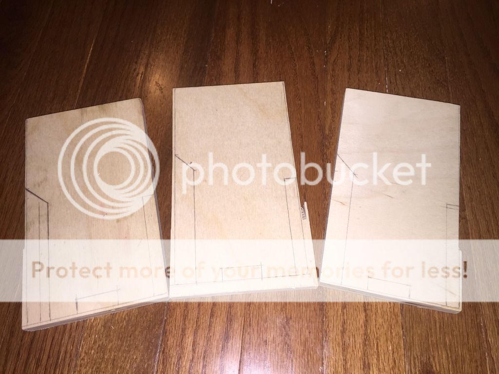
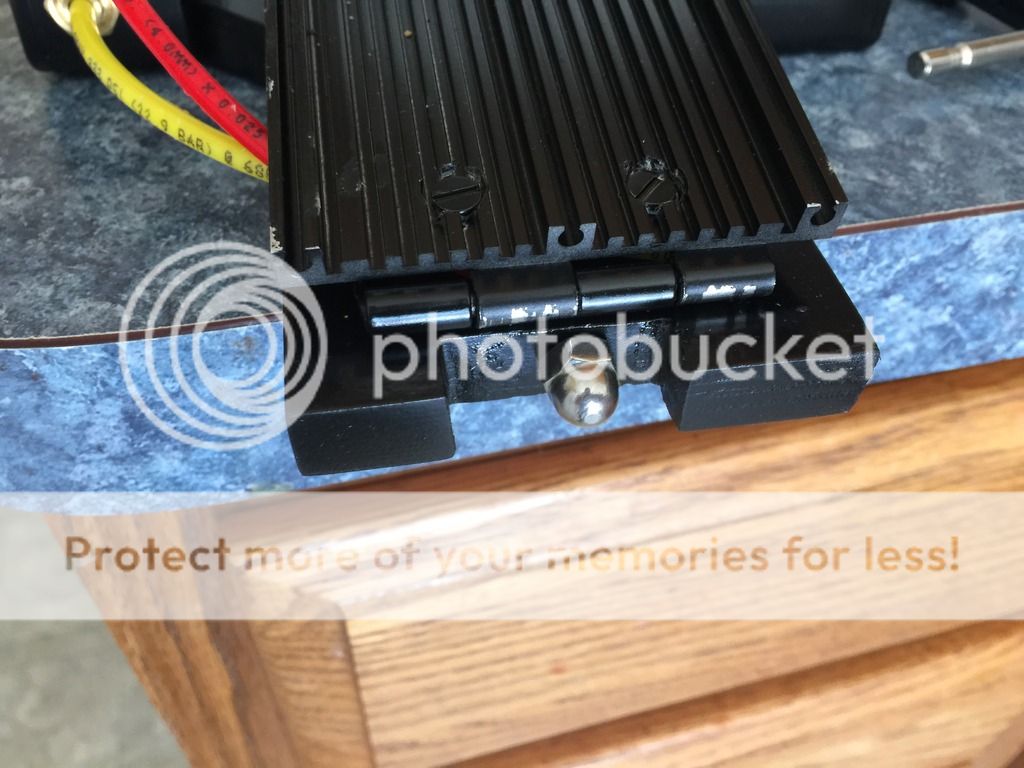
-The pedal bases. They're being made on 1/2" craft ply. I rough cut them with my circ and miter saws. I'll be heading to Alex's tomorrow to sand them and finish the cuts.

The greeblies I have left to procur aren't too hard to get. The only one that's got me back on the rocks as far as availability is tge Cal-R. I had a vendor, but a min order of $50 is needed to pyrchse through them and they frankly have nothing else I'm interested in.

Still on the way are the 15 pin d sub connecters and the d sub hood. I purchased grey but will paint them black. Also, linrose lamps are on the way and eventually I need to sit down and program an arduino to handle all the fun electronics stuff.
PssdffJay, jackdoud liked this
By PssdffJay
#4829677
Sonofa...

That was what I had started to do in late September, then Micah's son wanted to be a Ghostbuster for Halloween so I put it on hold to build that, then major life crap happened. Plus, I would have needed to learn CAD.

Looking forward to this. Might make me restart mine, but if you already have done the CAD work, I'd be very happy if you share it.

Subscribed!
By Hijacker
#4829710
Alex and I got a bunch done today.

Image
-First thing was to cut the base plates and sand the edges. Afterwards, we drilled the sides and installed studs. The project boxes were to match and held in with nuts and lock washers. The boxes were also drilled and tapped for the foster and legris fittings.

Image
-The black project box was also set up for the Omron sockets. I removed the solder lugs and Alex sanded the molded bottom flush. We then lined the sockets on center and drilled and tapped the box for 6-32 machine screws. On my way home, I stopped by a closing Radio Shack and picked up some lights to put in place of the arcolectrics.

Image
-Last thing accomplished today was to strip the outer fins of the vector plates. I need to smooth some edges with bondo before final paint. I did pick up some 2" hinges from Lowes as well, but the included self tappers were too long. I'll need to get sone shorter 1/4" tappers tomorrow.
#4829711
There is something wrong with my eyes. I'm seeing 3 of everything.
By Hijacker
#4830497
McMaster Carr. I have a shit ton of it since I had to order a min quantity of 5 ft. I can mail you some if you cover the cost of shipping to Canadaland.

I haven't gotten much progress done in the past week or so. I painted the boxes, skimmed in the ground down spots of the vector plates with bondo and dry fit some more parts.

I did get my piano hinge in and cut it down, I'll post pics of the progress soon once I clean them up and drill them for mounting.
By Hijacker
#4830612
Finally got some time to work on the pedals.

Image
-Relays came in and a pic if the bellows material.

Image
-I didn't like the available 2" hinges, so I ordered a piano hinge. The ears are 1/2" so there'll be 4 ears per hinge just like the screen used traps.

Image
-The hinges were drilled and countersunk for wood screws ( the countersink is on the side not photographed). I ordered some 6-32 bladed machine screws to hold the vector plates in. The hinge was drilled and tapped. The vector plate was drilled and slightly countersunk. Each screw is set at 1/2" from center and 3/8" from the edge.

Image
-The vector was dry fit and some bellows cut.

Image
-The vector rides high, but once the bellows is compressed enough to sit flush to the plate, it looks fine. I need to devise a solution to hold the bellows to the plate.
By Hijacker
#4831045
I haven't had much time to work on the pedals. But I was finally able to drill and mount the hinges to all three bases. Now I can finally start painting them! I've gotten up to the silver coat. I'll let this dry overnight so I can shoot it with some clear protector and then a final coat of black.

Image

And now for the moment we've all been waiting for! Or at least me. I don't know who else is aside from Phil and Alex.

Image
-I joined a group in RIchmond, VA called Hack RVA. They have a small CNC router. I was able to slot some time today to sneak over there and slap some 1/8" craft ply as well as my 1/4" ABS into the unit and start cutting panels!

Image

Image

Image

We had some depth issues with the router that were kind of unexplainable, but I just made some adjustments to the real time controller instead of having to reprogram the whole thing and just kept going. There are some goof ups where the bit drug across the surface instead of moving over it, but I can fix those spots with some bondo and strategic placing (most of the faces will be facing inside something or covered by another plate.

Image

Image
-I had the CNC leave tabs to keep the pieces inside the skeleton so they wouldn't pop around all over the place during cutting. I hadn't yet popped the cartridge pieces from the skeleton at this point as they required some dremelling to remove.

Image
-I went ahead and did a test fit of the main body with the base plate of the cartridge to see how much clearance was going to be to the side of the cartridge. It's a bit tighter than I had originally anticipated, but there's still enough room to be able to put the side plates on the cartridge I think.

Image

Image

I need to skim some bondo to the back of the ABS plates to smooth out the rough side and give the plates a bit more thickness. Each one is supposed to be 1/4" thick , but they look a hair shy of that by about a 1/16".
By Hijacker
#4831049
And now that I know that the files work and everything looks like it's gonna be a good fit, I give to you, the community, my CAD files.

https://drive.google.com/folderview?id= ... sp=sharing

These are based on Stefan's plans. I just rounded each measurement to the nearest fractional inch since that's what they would have been built on. I also built each around 1/8" and 1/4" sheets to be cut. The trap doors are cut in 1/8", but are layered to get the CNC pocket cut look if someone doesn't have the ability to cut them with a 3 axis. The only thing missing is the battery box, but that's because I felt it would be better to make it out of sheet aluminum than to make it out of 1/8" or 1/4" plates. I included guide holes for the DB15 connectors (and I'm still not entirely sure how well they'll line up in the end since I haven't built the track system nor mounted the connectors at this point). The connectors' shapes were pulled from data sheets on Mouser and i placed them per Stefan's plans. I also included pilot holes for the v hook, but you could take those out easily. I just felt they'd be useful for lining up the bottom plates when being stacked.
By Hijacker
#4831078
More progress on finishing the pedals today. I somehow managed to misplace a vector plate, so a new one is on the way.

Image
-All the base are belong to....I mean, they're painted.

Image
-Then it was just a matter of reattaching the project boxes and cutting some nycoil tube.

Image

Image

Image

The d sub housings are still on the way. Intertex apparently forgot to send them once they filled a backorder on the same ticket. Once they're in, I can attach the 26 pin cables to the headers.

Also, the vector plates I still have are currently going painted. I need to get to Lowes and pick up a hole saw so I can make some mounts for the bellows. I plan to epoxy the circular part of the wood to the bottom of the vector plate and then use a tapping screw hidden under the plate to attach the bellows.

I'll leave weathering to Phil and Alex on theirs, but I'll be doing some one mine and I'll need to dig out my dry rubs soon so I can start getting this thing looking proper.

I also picked up a bench top sander and cleaned up the trap bodies. I'll be starting on them soon. Gotta give the pedals something to connect to!
alphabeta001 liked this
#4831079
Those are looking first class, dude.
By Hijacker
#4831088
Thanks for the kind words!

AJ, feel free to upload the CAD files to the site. I can make some pictures of the layout if necessary.

One of the vectors finished drying so I went ahead and attached it.

Image

So far so good!
User avatar
By pyhasanon
#4831090
So jealous... waitaminute, one of those are mine! Bwahahaha! Anywho, still jealous of your skills... need to drive over there sometime to help out and learn some stuff...
By Hijacker
#4831151
Got a little more done. First was to add the 10-32 acorn nuts to the pedals.

I didn't really want to glue them on, so I drilled and tapped to accept a 10-32 stud. All the wood screw to 10-32 studs were way too long, and the brass inserts required drilling out a 5/16" hole, which left less than an 1/8" on each side of the hole. If my bit was off a hair, I'd ruin a pedal. So I decided to tap the wood directly for a 10-32 stud.

Image

Image
-I then took a 10-32 bolt and ground the head off to get a short stud.

Image
-The acorn nut and stud looked good test fit.

Image
-A little paint for the finishing touch!

I have some more I can hopefully post tonight.
alphabeta001 liked this
By Hijacker
#4831174
My order from intertex finally arrived, so that means I have d-sub hoods and 15 pin connectors as well as the push button I plan on running in these pedals.

Image
-Already painted one to test fit placement on the nearly complete pedal. I still need to spray the interior of it as you can see the grey even with the 26 pin cable shoved in there.

Image
-Male and female 15 pin d-subs.

Image
-This made me happy. I haven't modified the opening in my panels at all. Completely raw from the CNC and it's a perfect fit.

Image
-These switches were the hold up on my order. I had picked them up because they were side feed push buttons. This should supposedly make it easier to mount on the pedal and hide inside the bellows. I had no clue how huge they were though. I may have to devise a way to sink them into the pedal to give a bit more swinging room. As of now, the pedal only travels about half an inch on the outside swing before it contacts this lug.
By Hijacker
#4831453
Yay! More progress! I'm still waiting on my next GBfans order to replace my lost vector plate, so I'm kind of held to working on two trap pedals right now. I finished the physical portion of one pedal today.

Image
-First was to paint the d-sub hoods black and secure them. A self tapper was used after I drilled a pilot hole. I forgot to snap a pic, but I secured the ribbon cable by drilling a pilot hole through it and then securing it to the hood and project box with another self tapper.

Image
-Two zip ties. This cable is a bit tight and I might replace it.

Image

Image

So far, I'm pretty happy with this one. I'll be finishing number two soon, and then once the new vector plate comes in, I can finish the third.
By Hijacker
#4831472
Thanks VS! It's been a fun ride doing the pedals so far, and I can't wait to start on the traps soon. I have a lot of prep work before I can start building the trap bodies though. The ABS I bought was supposed to be 1/4" thick, but it turned out to be around .2". All of my CAD files were designed around 1/4", so I'll have to skim some bondo on to the backs of the plates and sand them smooth. Fun times ahead -_-

But I did finish the second pedal this morning.

Image
-I ran out of tapping screws, so I decided it was cleaner and easier to just use some of the excess 4-40 screws I have from 26 pin grey header. It's a lot cleaner and easier to install too.

Image
-An oft overlooked detail I noticed. Not sure on the GB1 pedals, but I have noticed that the GB2 pedals have these screws painted black. Granted, they used wood screws where I used machine screws. But that's a sacrifice I made from authenticity for the sake of being able to do a proper tear down and rebuild if necessary. That, and I realized they were wood screws after I had drilled and tapped for the machine screws.
Possessed Sony Discman

So it turns out you can give power via ANY channel[…]

New PKE build

One more video demonstration with handheld operati[…]

Yep, and nightmare on elm street dream warriors.

You can see our Paranormal Boots in action here: […]