By Hijacker
#4832221
Not much to report recently other than I've been busy. Just not on trap stuff. I did, however, find some time to order a nifty little part that I feel is a solid detail for the pedals.

I wasn't very happy with the close enough red lights I had purchased from Radio Shack. They looked ok, but I really wanted some arcolectric lights. I did some digging and found Newark had the 2.2 LED versions available. No need for high voltage for these suckers! The only thing, is that their UK subsidiary, Farnell, stocks them. So shipping was a bit of a bitch for just a few little lights.

Image
-These suckers are the shit!

Image
-I also like that they're much shorter than the old RS ones as well.

Image
-The difference is really apparent when you look at them installed side by side. I really think the arcolectric pops and conveys a bit of class.
alphabeta001 liked this
By Hijacker
#4834043
I'm back! Now that school has wound down, my pack's electronics are installed, and I have a bit more free time, it's time to get back to work on the traps.

First thing, my new vector plate arrived from GBFans to replace the missing one for my pedal. I chopped the edges, drilled the mounting holes 1/2" from center and 3/8" from the edge and gave them a clean counter sink taper. Then I drilled and tapped the hinge for 6-32 and installed! The pedal is still unpainted, but that'll be fixed tomorrow. I"m just excited I was able to at least find the time to attach the raw plate. I also ordered some extra dry rubs and vinyl labels from one of the users and they've already found their use on the pedal.

Image

Image

I still need to cut and attach some bellows for this pedal and Phil's pedal. I also came up with a better side feed push button switch I found at Lowes.

Image
-I was able to procure the GB1 side knob. I still need to finalize what I want for the front knobs.

Next step is to reorder some 1/4" ABS and get back to the CNC and recut everything. The previous stuff being 0.19" is just screwing with me and I hate it .
By Hijacker
#4834923
Time to get backon trap building!

Image
-NOS Cal-R MC250s. They're 90s era I think since they're an RER70 and not an RE70 as they were advertised. But they'll do nicely.

Image

Now for the main course. These are shots of a rough assembly of the .18" material. I have new, .25" sheet to cut, so this was just a practice assembly. The body and cartridge have a lot of screwheads that need to be shaved and skim coated in bondo. I think for the next assembly, I'll use screw nails. They can be hidden a bit easier and can hold tight since they screw in as the are hammered in. I also think I'll back up the nails with some epoxy or super glue

Image

Image
-This was why I was upset that the previous run was done on .18" sheet. All my dimensions were designed around .25", so extreme gapping is a concern for some areas. I need to fill in the front with bondo to reach the edge of the base anyways, so this can be covered and hidden.

Image

Image

Image
-Shameless plug for my favorite cable manufacturer. Okonite. Also, the baseplate is a hair wider than the width of the body thanks to the thickness issue. Covering the haircell texture and screwheads should hopefully fix this.

Image

Image

Image

the metal to make the track is on its way as are the new fasteners for the final three. I'll do some cleaning up work on this tonight so I cam start testing fitment for the doors and bar graph housing.
By Hijacker
#4834947
Skimmed in some bondo and smoothe out the sides a lot on this build.

Image

Image

Image

This was the first coat before sanding. I normally do two coats minimum, but this coat was particularily poor due to the bondo setting in quicker than it should. The newer cans have white hardener which is impossible to get the proportions right over the old red hardener. It ends up congealing before I can get enough on

Image

Image

Image

Image

Image

Image

Much better! These shots were after the second coat, sanded, and wiped down with a damp cloth. There are still some spots that need attention. Some can be covered by metal plates. Some will need some extra filler and sanding. I was hoping to get the inner riser of the cartridge done today, but I didn't have the time. That, and assembling the bar graph housing will happen later.
By Hijacker
#4835077
A minor half update: I began work on the battery box yesterday. I need to even a couple bends and flatten some sections on the belt sander, but it's coming along.

Image
-Step one: bend this frakker into a rough shape. For the next three, I'll make a jig to make this easier and more uniform.

Image
-The bottom plate was cut and sanded in shape. Attached with 6-32 button heads.

Image
-It isn't attached yet. I'll use some 6-32 countersunk panheads drilled through the sideplates to hold it in place. I'm deciding if Inwant to keep the back tabs (mated with the interior plate for the connector and handle), or sand them off. It's not a detail you can make out easily. I was originally going to use them to secure the box to the interior plate, until ai noticed the panheads in the prop bay ref shots.

Image
-I'm not sure if I like the 22 gage sheet on the sides. It looks too thin. I might see if a slightly thicker sheet is readily available. I think an 18 gage should be about right.

Image
-The tabs needed a slight reduction in size to fit properly, but this greeblie will be ready to go as soon as I get some 4-40 button heads.
User avatar
By Grimmy GB
#4835158
This is turning out so awesome! What are you using to make the bends in the metal?
I really need to find a way to make clean, straight cuts on the metal plates. In failing miserably. Yours look freaking amazeballs.
By Hijacker
#4835169
I've been at my parent's all weekend, but I found some time to use my dad's drill press and get the mounting holes ready for the battery box and the small vector plate.

Image
-Drilled and countersunk for the pan head bolts.

Image
-Now it's hidden!

Image
-Although I think I placed it in the wrong spot when I compare to the prop bay shots.

Image
-Aaand the vector is done. Now to get some button head 4-40s and mount this.
By Hijacker
#4835990
I was not happy with the overall uniformity of the battery box, so I decided to make a shaping form.

Image
-I took two 2x4s and glued them together and then shaped it on my belt sander. I also shrank the dimensions to account for the thickness of the sheet metal.

Image
-It came out a lot better this time around.

Image
-A comparo shot with the janky one on the right. I need to remove some of the plastic and have the box sit flush with bottom plate. Then add a weld line to the box as the bottom was welded on the screen used prop. I'll need to update my CAD files to make the change to let the box sit flush with the bottom plate.

Image
-Skate bearings!
alphabeta001 liked this
By Hijacker
#4874962
So, a year later, I have....no updates! The past year has been pretty tough time commitment-wise. The project isn't dead, just delayed. I scrapped the idea of doing this as a CNC project, and instead redesigned it as a 3D print project. I was never happy with the CAD files, and the way they went together. Going full 3D print will help fit and finish. I've taken my old CAD files and started working on some solid files. They're still on the first pass and have a ways to go, but the nice thing with working in 3D space is doing test fitting virtually. I've already been able to isolate and correct a handful of errors in the original plans. There's a company locally that I will eventually contact about doing full scale printing for the cartridge and body, as I'd rather have them printed in one piece than in parts to be stitched together.

Image

Image

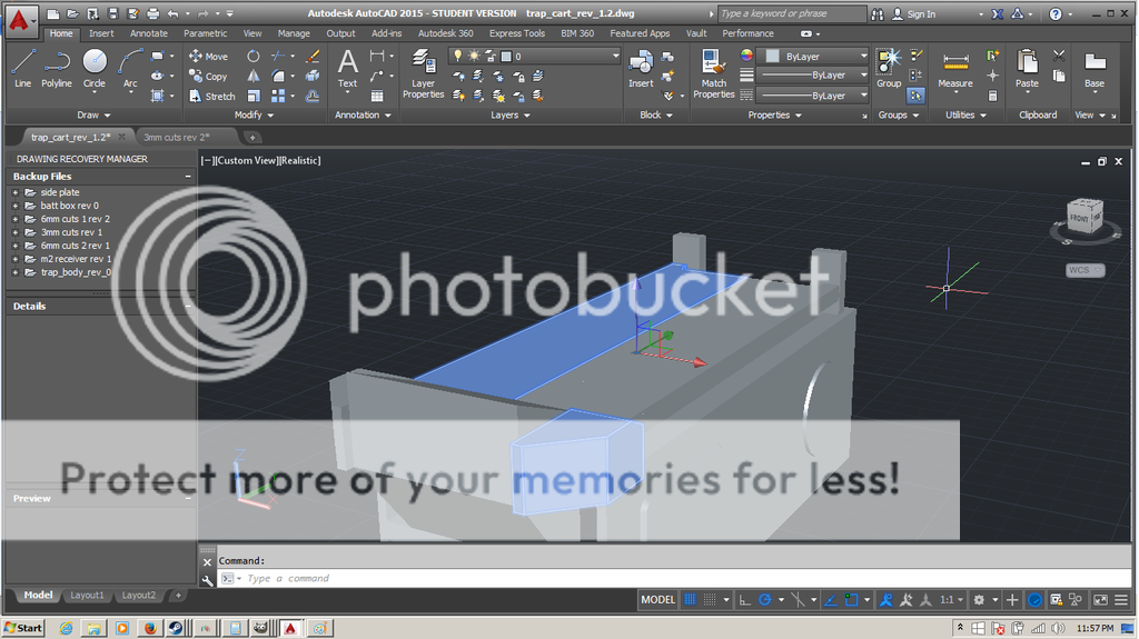
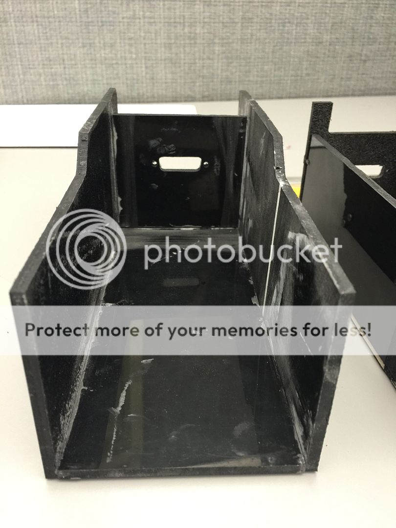
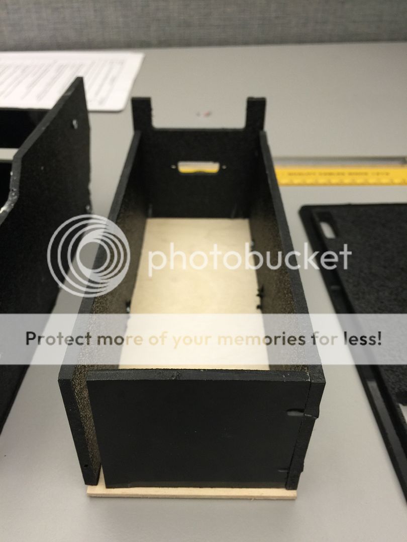
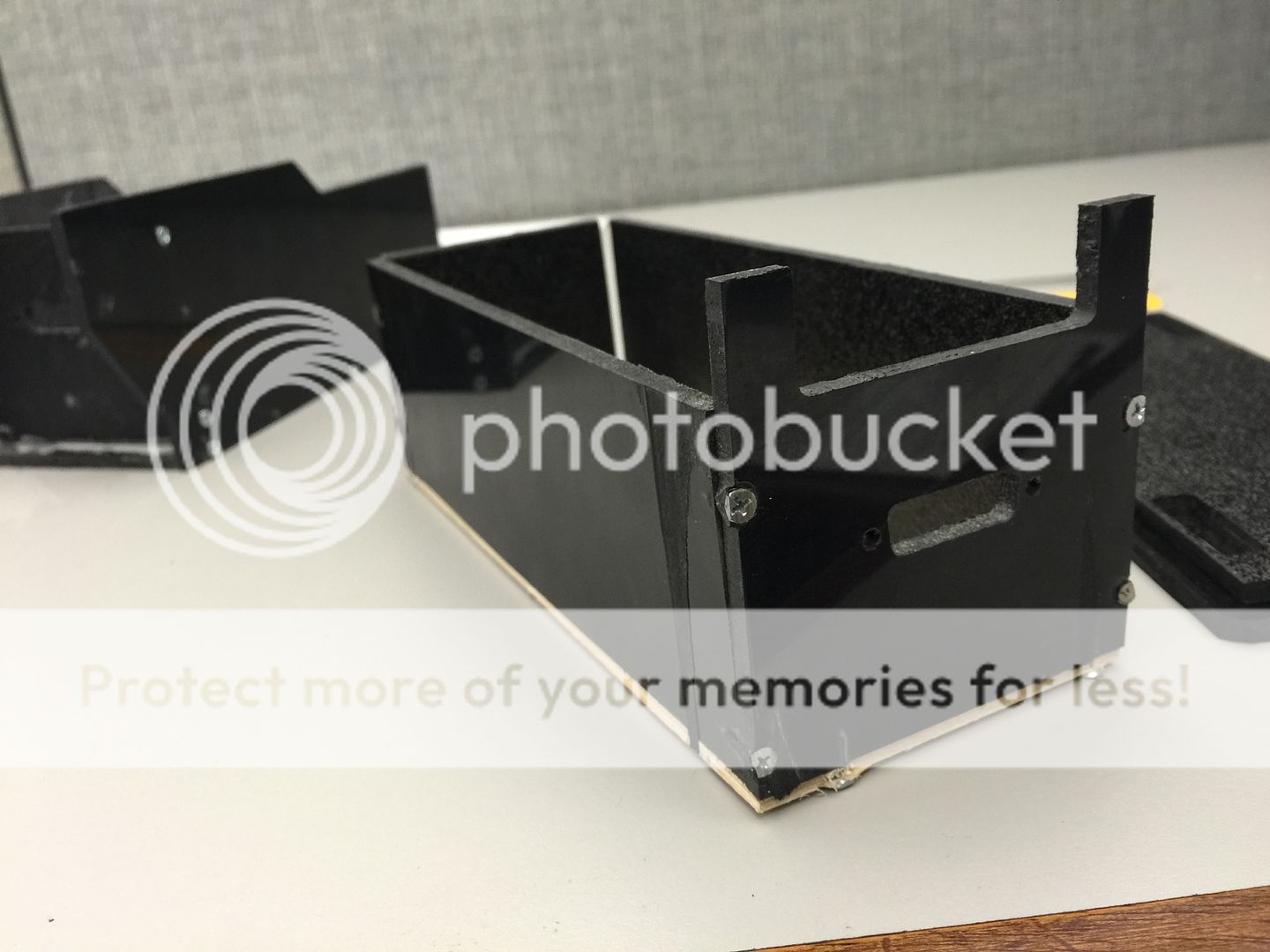
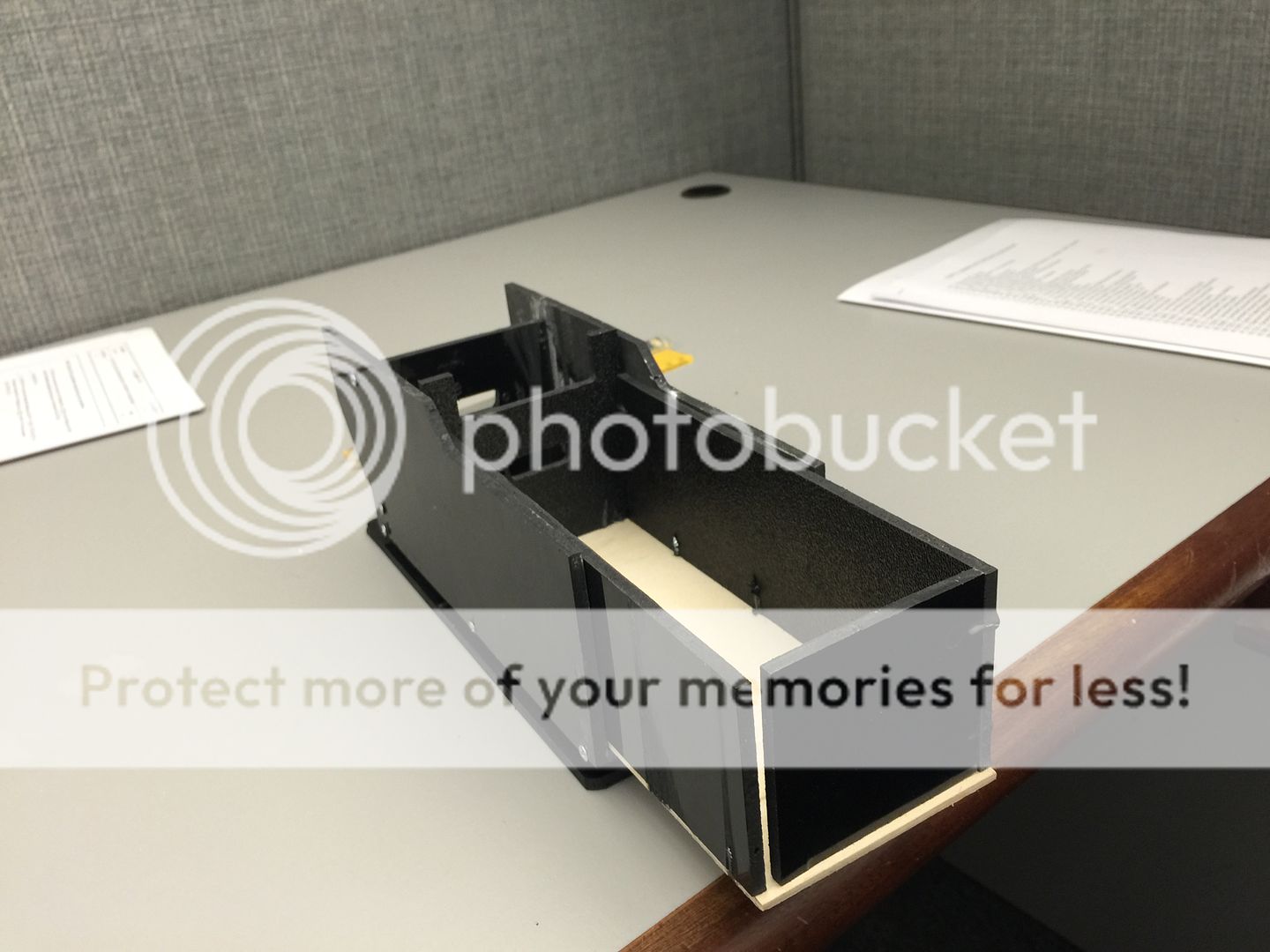
The doors, ears, and bar graph housing have been modeled and fitted. The cartrdige is 90% done. I want to finish some internal reinforcements before I add the floor of the trap.

Image

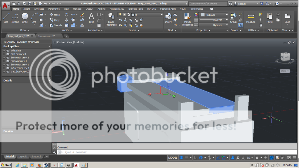
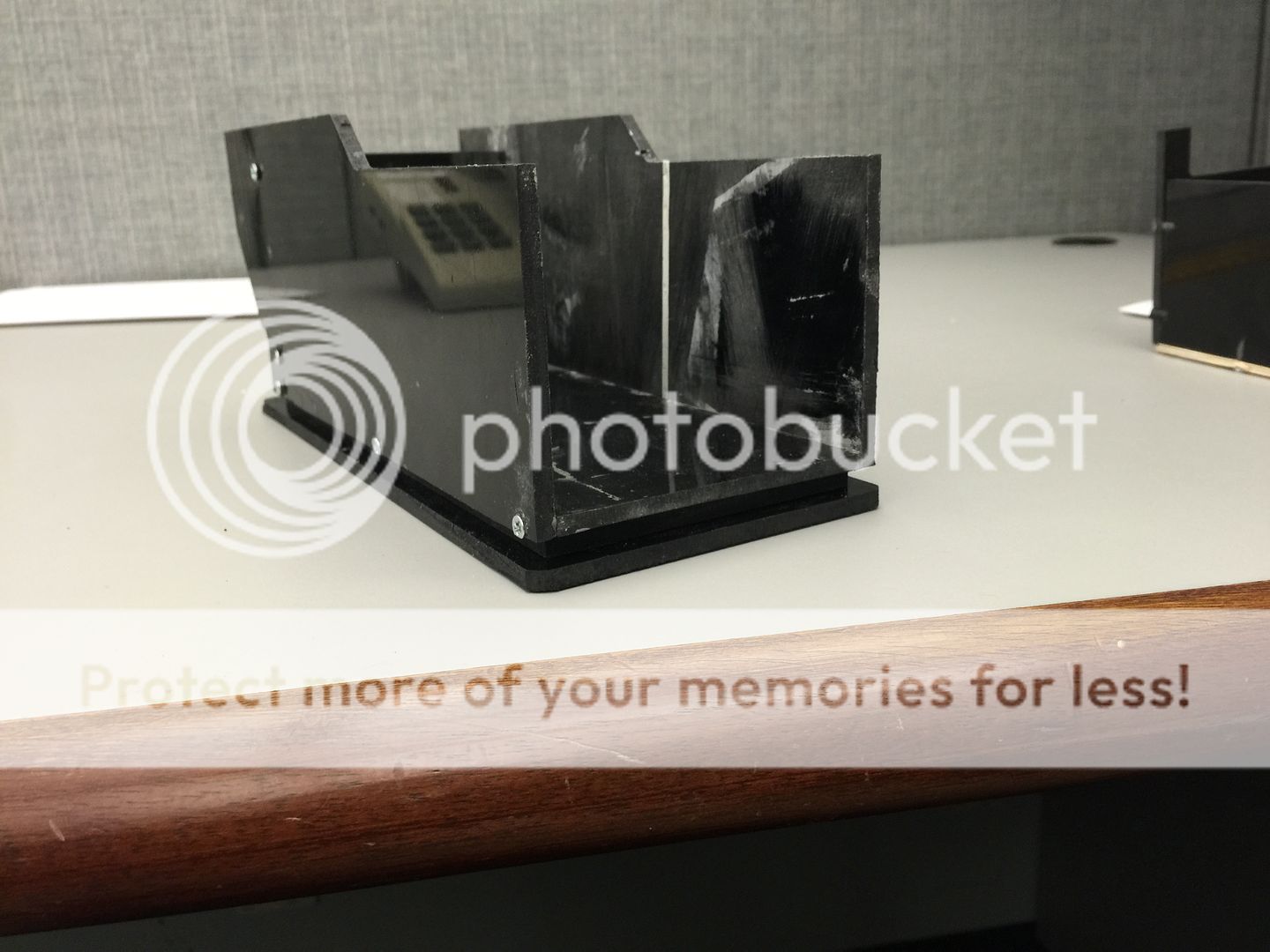
The body is more or less done. I have to decide how high I want it to sit so I can get the wheel recesses placed.

A few weeks ago, I was out of the house, and like an idiot, had left my trap pedal in reach of my three year old. He managed to drop it and break the relay.

Image

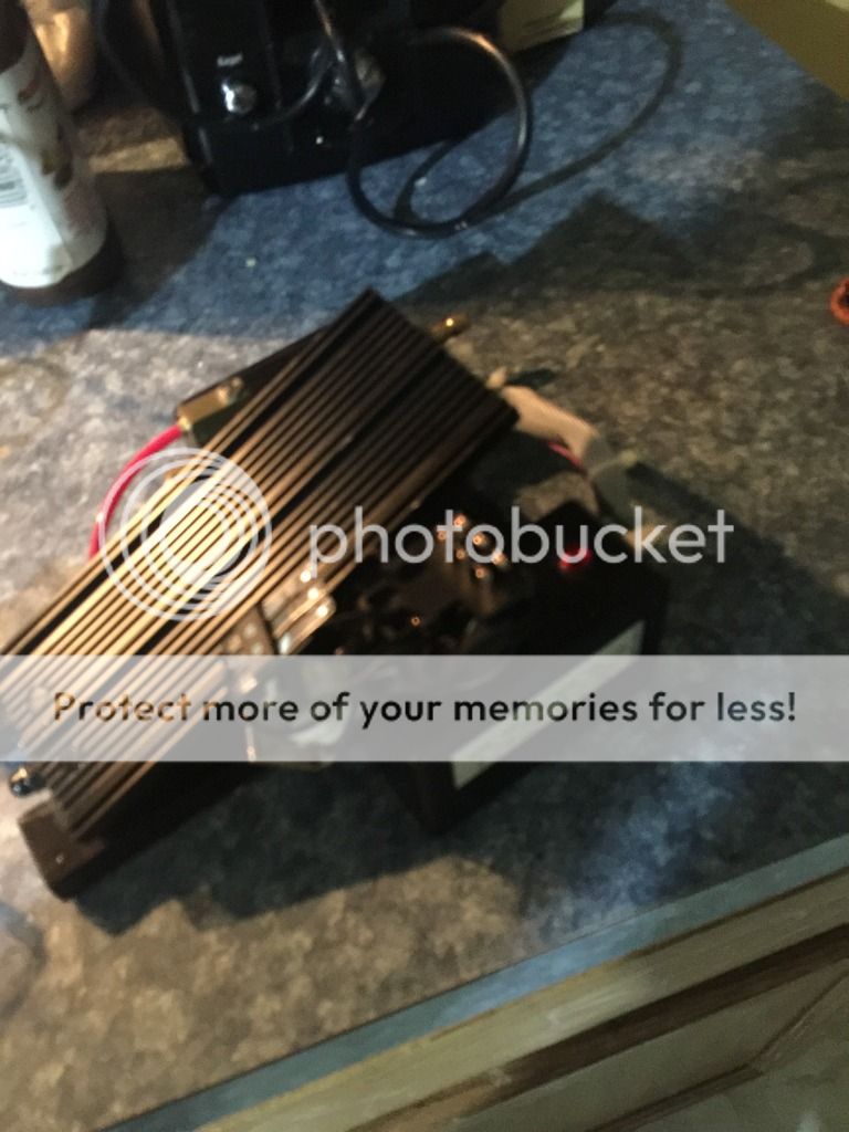
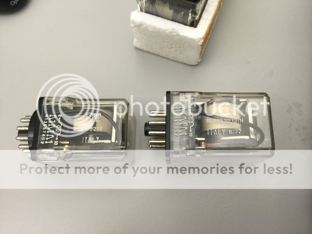
The rest of the pedal survived nary a scratch. I hated that Kest relay anyways. I took to ebay, and on the first day, managed to find someone listing ITT RM833212 relays for a reasonable price. I had previously spent months searching with no luck, so I was REALLY suspicious that this was too easy. Regardless, I ordered the relays. Unfortunately, there was a mixup at the seller's warehouse, and I was sent a set of relays that were /N relays. Not sure what that means, but we joked at the office that it must mean nuclear. Hehe.

I contacted the seller and he corrected the order quickly.

Image

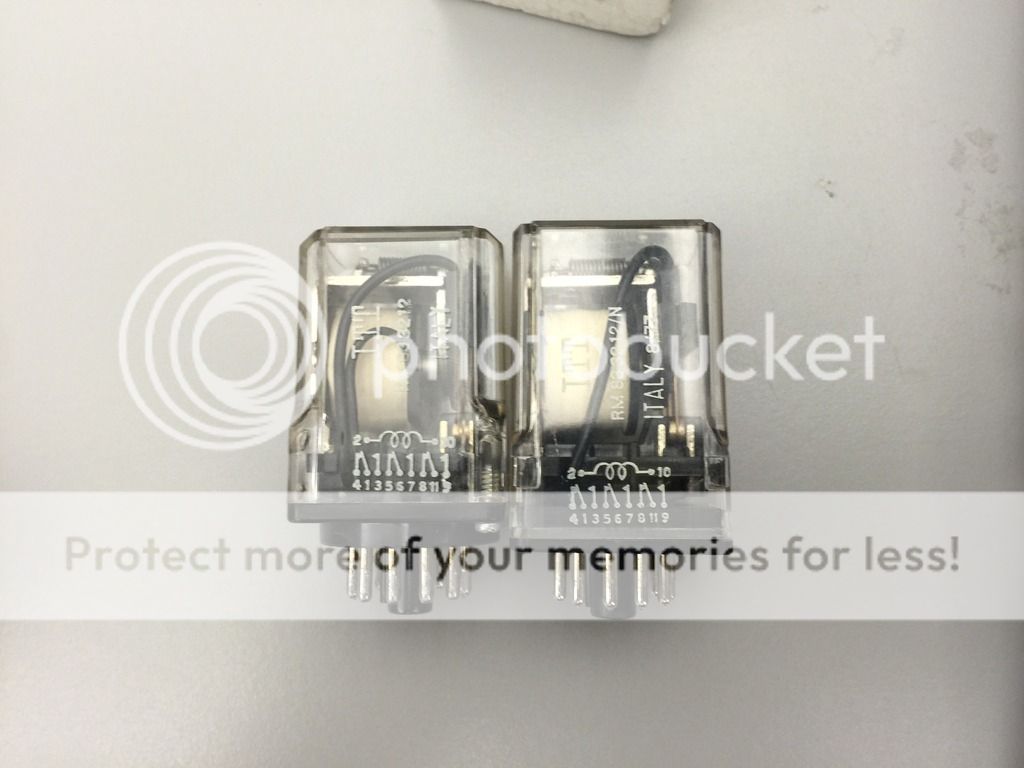
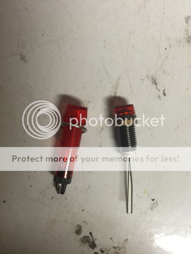
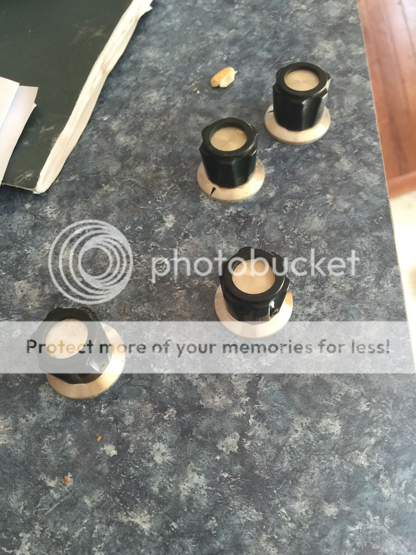
The standard relay we want is on the left. The /N is on the right. You can see the base and housing are different. Overall, they're the same height, but the housing of the /N are longer to accommodate the circular standoff for the standard relay. Also, the clear housing on the /N is a snap on, while we desire the screw on housing.

Image

Image

Image

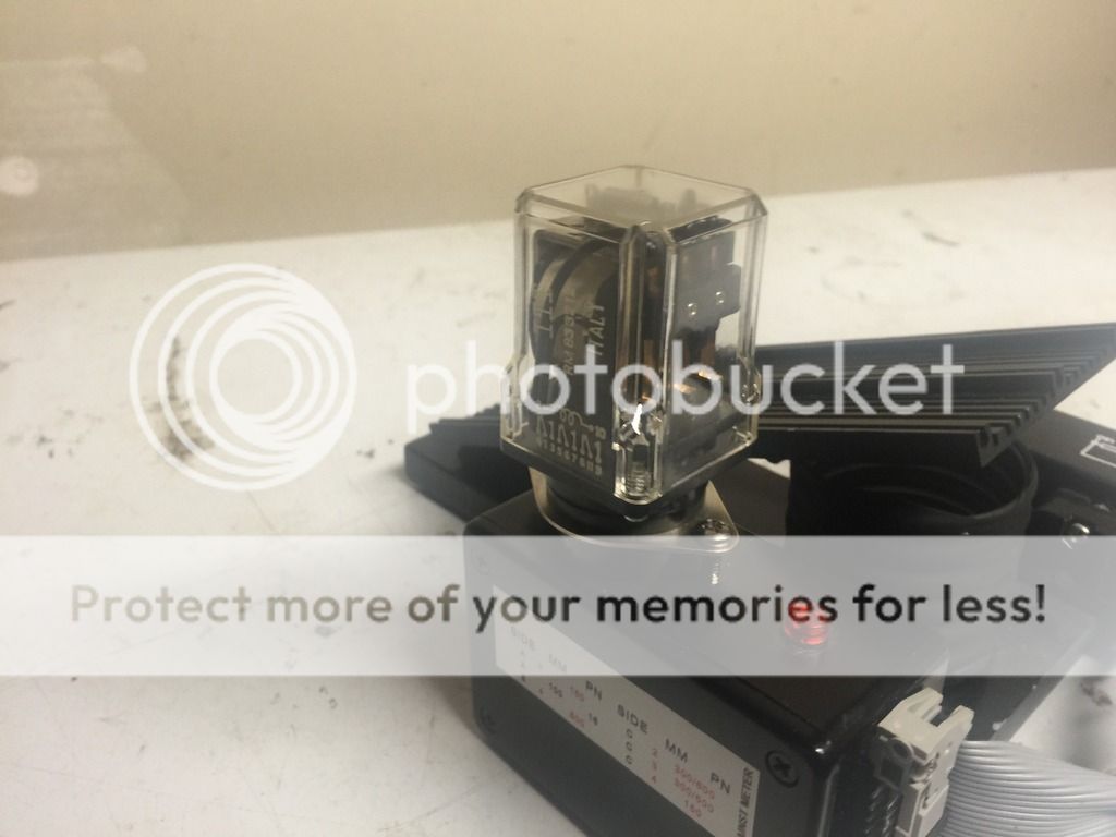
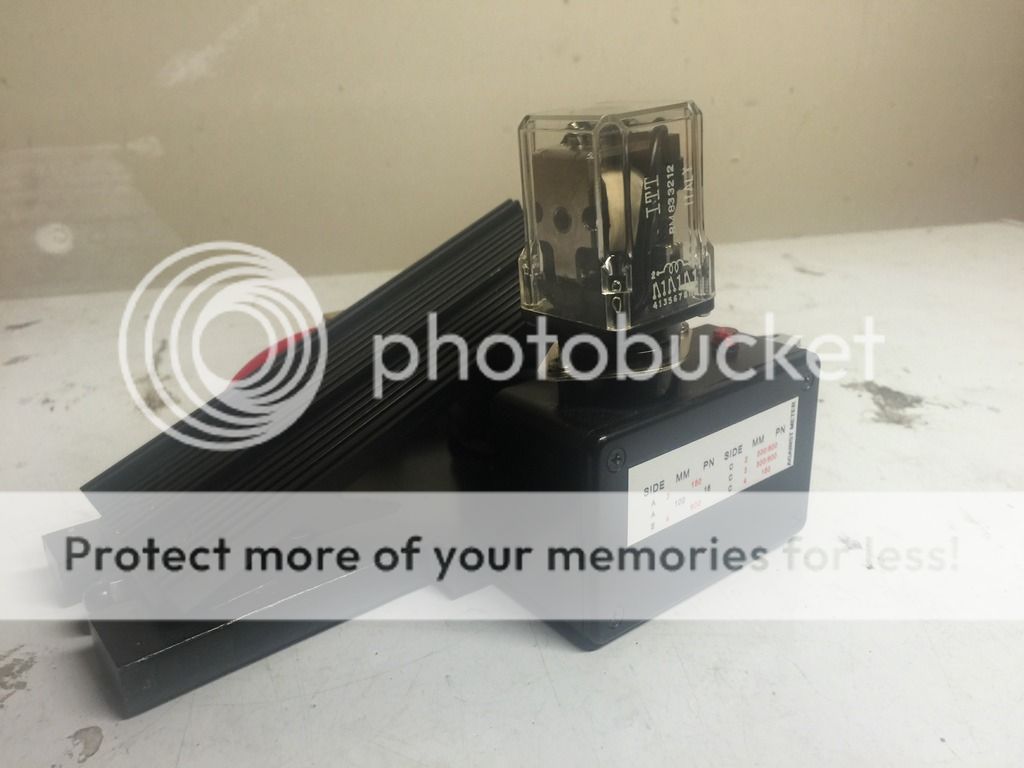
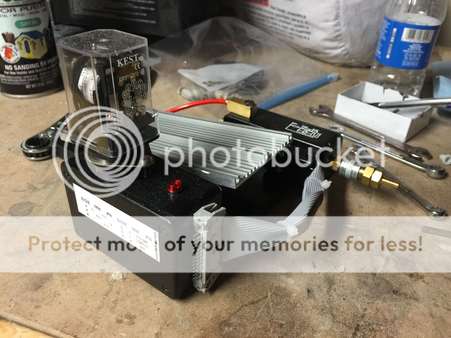
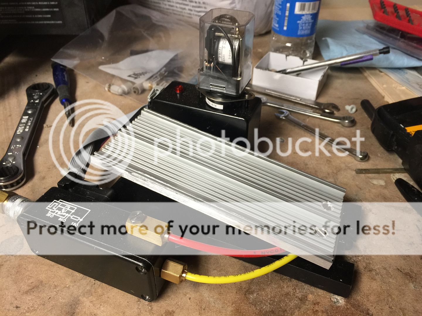
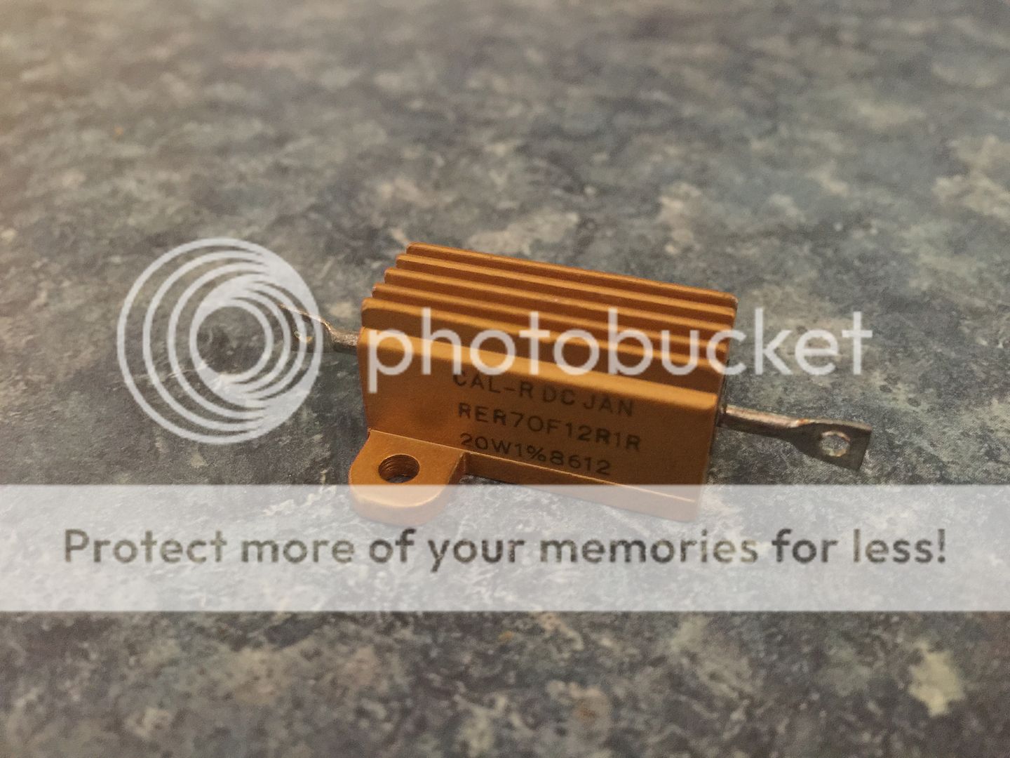
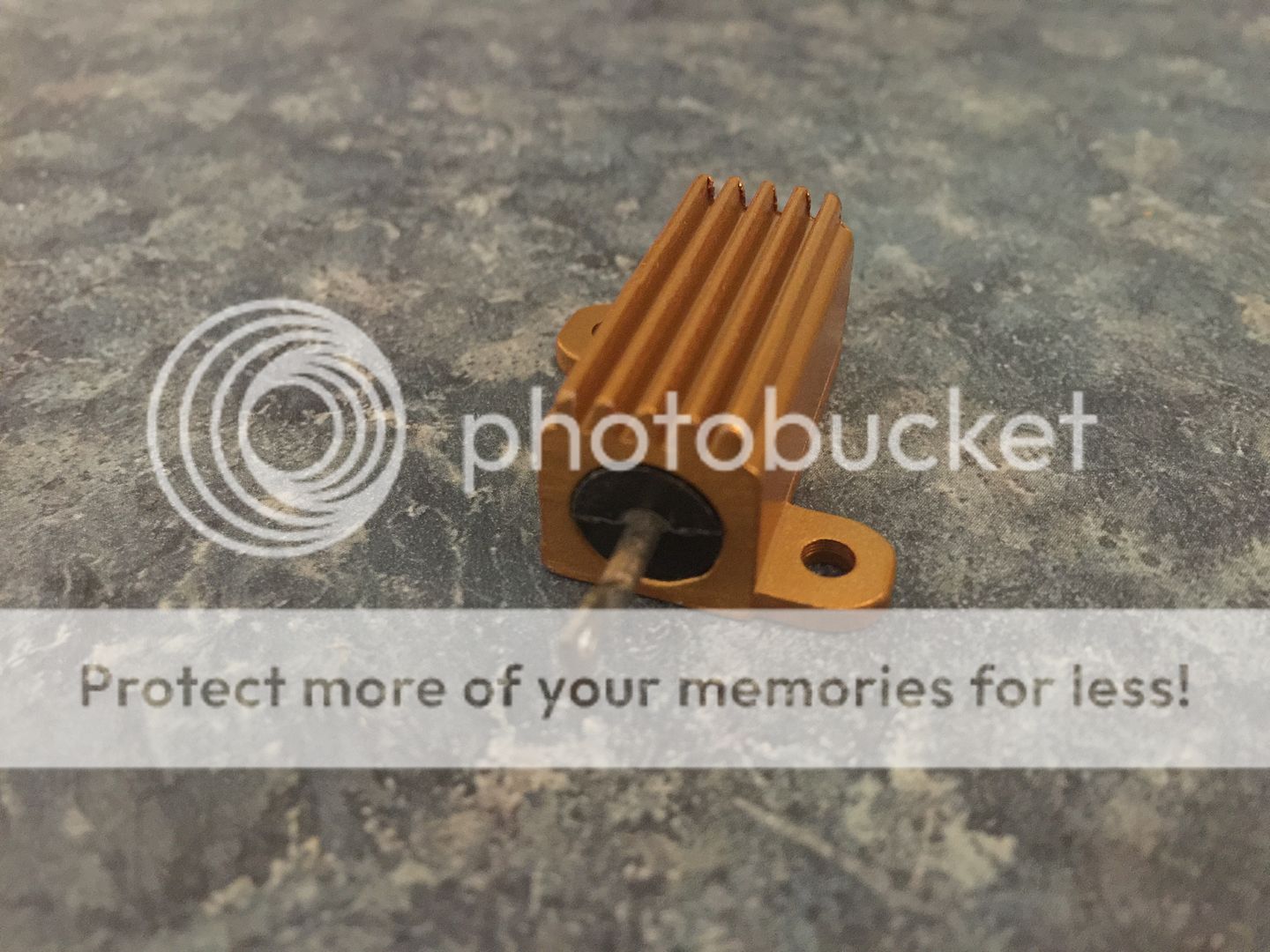
I'm debating on getting a new 11 pin socket base and retaining the solder lugs to integrate the relay into my electronics design. Unfortunately, it would necessitate going to a 12+ volt system as the pickup for the relay coil is 9.6 V, so a simple 9 V system won't cut it. Another neat thing too is that I had excess vintage clippard tubing from my pack build, so I tossed that on the pedal as well. I'm currently finishing making mounts for the bellows that will also double up as the switch contacts for the electronics.
Greetings

http://i.imgur.com/1kB7fOZ.jpg

I love that people are still making these packs. I[…]

For the legacy shell, what aspects are damage that[…]

At the moment my interest would be what sorts fo[…]