#445101
So, after building the ghost trap last year i knew it would only be a matter of time before 'the itch' would come around again and, well, it wasn't long before i was back deep into this site reading up on which way to twist the ribbon cable and what angle the screws in the thrower barrel should be.

Although most of the hard work has been done by numerous people before me it didn't stop me spending a ridiculous amount of time trawling through the forums. I'm too much of a perfectionist to just cobble a pack together, which meant that this was going to: A. cost a lot; and B. take a long time to collect parts for. Which it has. And did.

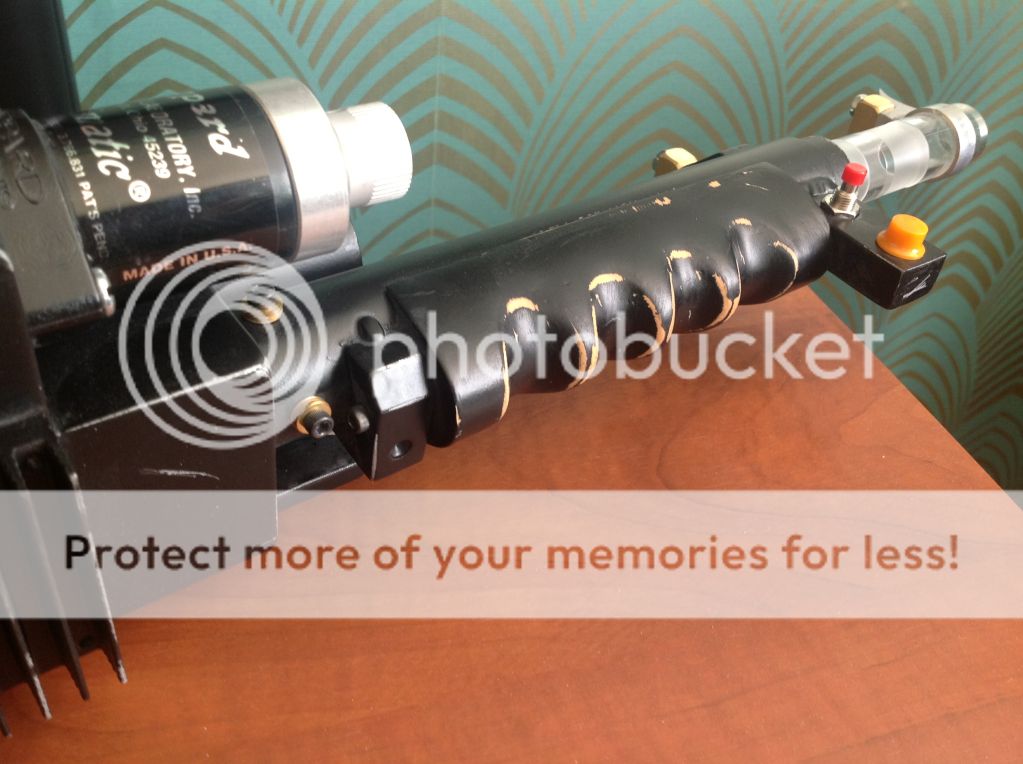
I decided to go with the thrower first as i knew it'd be more time consuming and that most of the parts (in the UK) were easier to find than pack parts. And because i'm familiar with the high quality of his parts i decided to go with Nick-a-Tron's thrower kit. I didn't record a build log as although i love reading them myself i didn't think i'd be bringing anything new to the table. Although there are one or two things i'd like to show so i'll include them in the detail shots.


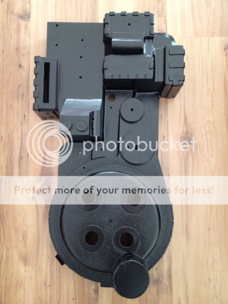
Now although the thrower is basically finished i haven't got any pictures of it yet, so for now i'll be posting my progress of the pack build (which i'll hopefully record the build of). I'll be going for accuracy to the GB1 Spengler pack and metal parts where i can. So, here's the start of my pack:

Image

Image

This is my metal MMM ion arm (which is amazing by the way, thanks Colin!) which came with a hole for the PH-25 and a tapped hole for the elbow. I had to drill and tap the holes for the cap and the resistors (10-32 and 4-40) which wasn't a problem as the whole process went a lot easier than i thought.
I've also got the ion arm cap from MMM, but in the [lengthy] process of fitting the blue tubing to the resistor and Clippard I managed to completely shred the thread on the cap (that bend in the tubing is really tight!). I'd tried going by the reference photos again but as the tubing was too short it kept kinking (did anyone else have this problem?), so i had to keep trying again until i just used a slightly longer length. I did try epoxying the Clippard back in but this didn't work, and because i'm a perfectionist i'm willing to fork out another $30 for another cap. Well, at least i've learned my lesson this time...


This also leads on to how i modified the SMC elbows to look more like the Legris versions. I've seen a couple of tutorials on here with good results so decided to give it a go myself.

First i removed the little plug from the front of the elbow. This just pulls right out with enough force.

Image

Once i'd done that i painted the elbows with Plastikote grey primer (the kind with the twisty cap) and left to dry. When they were dry i cut 5mm brass tubing to length (4mm internal diameter, which is the same as the thinner yellow/red pack tubing) - i eyed this up and compared with reference photos to judge the correct length. I was able to cut the tubing with a hacksaw as the uncut end would be the one hanging out of the elbow. I just dropped a glob of 5 minute epoxy into the elbow and pushed the brass tubing into place and left to cure. Here's another shot:

Image

[The primer was tacky for a while for some reason, so you can see the odd fingerprint on some pictures as the paint wasn't dry even a day later. It did dry with a slightly glossy finish though so i'm happy not clearcoating it as i thought i'd have to]

I'm really pleased with how these turned out. They make a massive difference compared to the stock elbows and it's so simple you've got no excuse not to do it!!


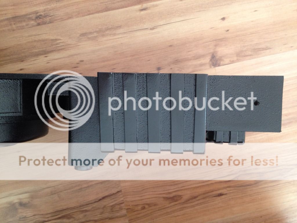
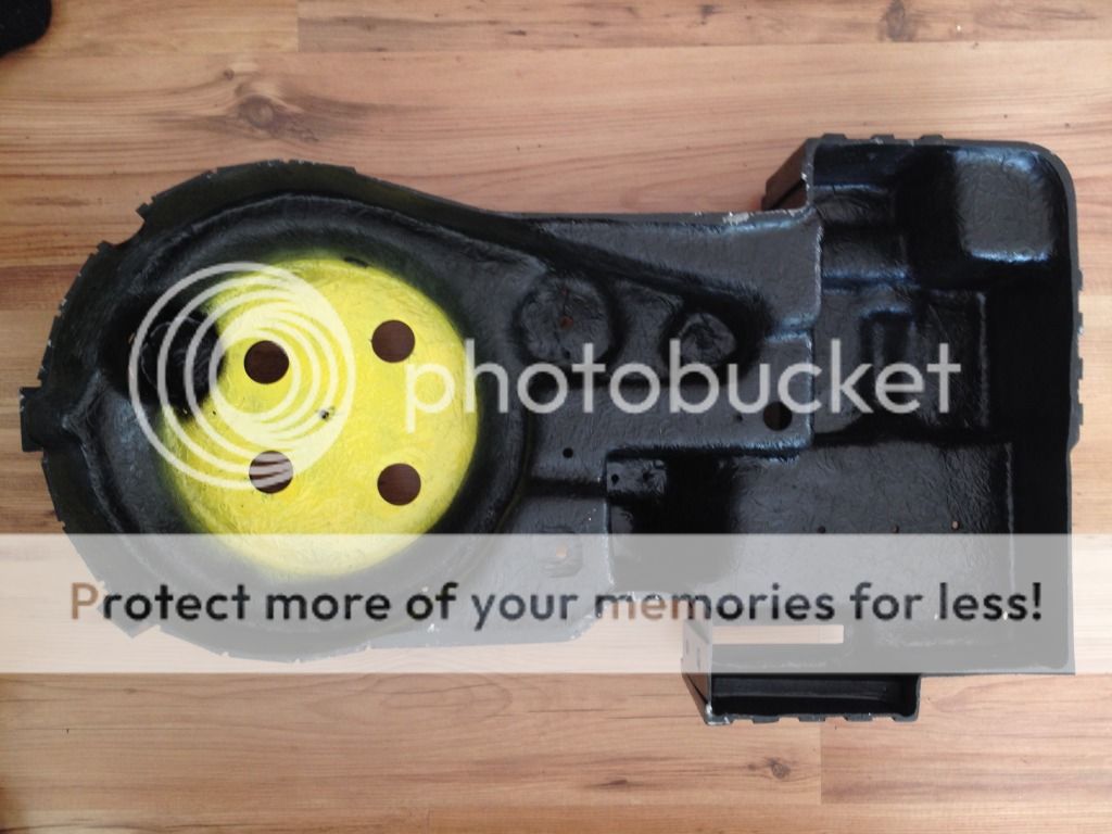
This is another great metal part from MMM, the HGA. Due to the different arrangements people ask Colin for this (understandably) came without the holes for the fittings drilled, and since i'm aiming for Egon's pack i drilled the holes offset:

Image

I eyed this up from the reference photos and on second glance i think they may be a little TOO offset, which may reduce it's accuracy but i actually like it more somehow?!

Image

Image

That's also one of JoeLuna's fantastic metal labels on there. It's the first one and i can't wait to fit the rest to the pack it looks so good.


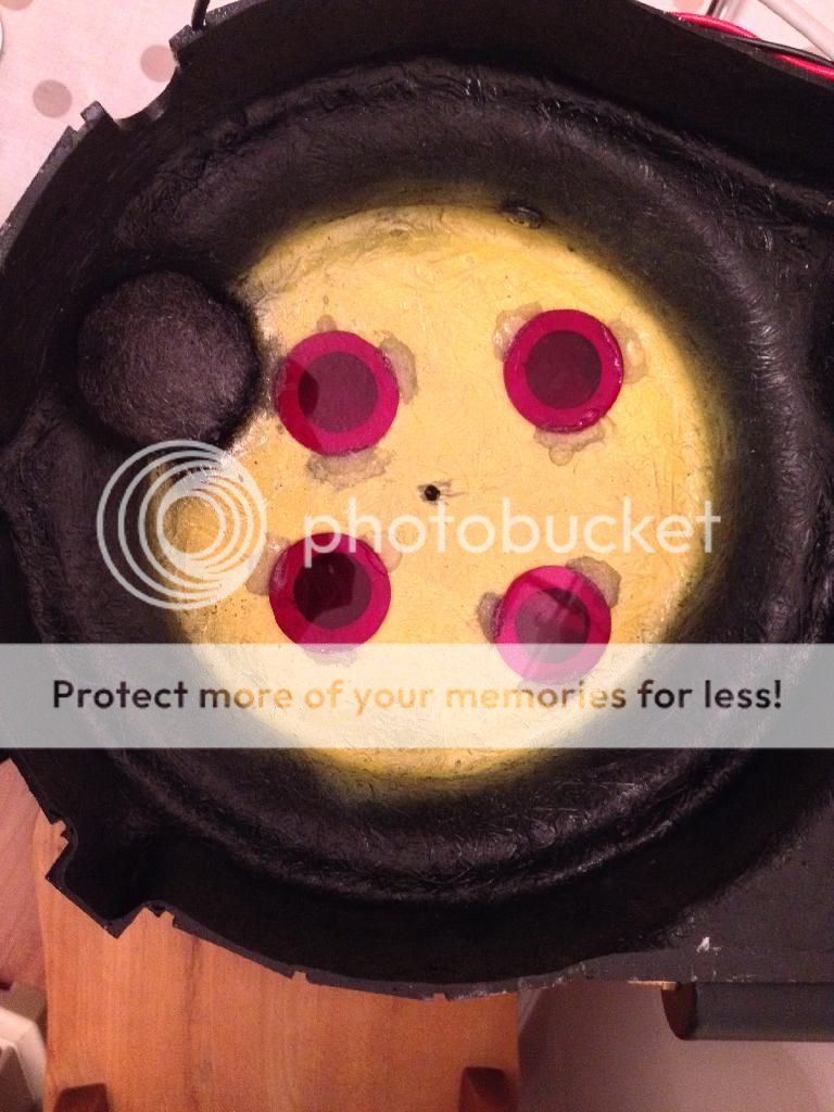
Here are the rest of the parts all together. As you can see i've also got the metal (MMM again) beam line, filler tube, PPD and vacuum line all painted up and ready to fit.

Image


So that's it for now. I'll be posting more as the pack progresses, and when i fit the last few parts to the thrower i'll be posting photos of that too.

Thanks for reading,
Dan.
Last edited by bromie on June 19th, 2015, 10:14 am, edited 4 times in total.
#445112
Ohhh, i didn't even notice from the reference pics that i was missing something. So what's this bit, the 'shell'?


;-) I kid. I'll hopefully be using Nick-a-Tron's shell. Although he's got GB2 semi-heroes ready to go at the minute i've been told he should have GB1 heroes ready in a month or so, so i want to hold out for then.

Lately i've been looking around again at the (amazing) shells on here but decided that it's not worth forking out the postage from the US, so although it's killing me i can wait for Nick's.
#445145
Haha! Thanks for the compliment Wharin!

And i used Plastikote again for the thrower and pack. For the thrower i bought (what i thought was) standard grey primer:
Image
My thrower consisted of the resin body with aluminium rear handle attached and Apoxie Sculpt fake welding, with the aluminium front handle (with attached ears) and all other resin parts separate (because of the different materials i wanted to make sure the paint was going to stay).


Like i said the primer wasn't grey like i thought but more of a cloudy clearcoat. I gave all the parts, especially the metal bits, a quick sand in all corners (important if you want the paint to stick well) with fine grit sandpaper to help the primer grab. I then scrubbed the parts in soapy water and rinsed and dried throughly. Even as you're drying the parts make sure to wear rubber gloves. You don't want to contaminate the clean finish with grease off your hand as this will prevent the paint from adhering. I then gave the parts 2 coats of primer.

Once that was dry i gave all parts about another two coats of PK Metallic silver (for the weathering later), and once THAT was dry about 3-4 light coats of PK Super satin black. With the top coat i made sure to just spray light coats from about 20cm until the parts were evenly painted.

For the pack parts above i did the same except without the silver undercoat, as they're all metal anyway.


I think the important things are:
~ Don't spray too heavily (if you think you're not spraying enough you're doing it right) - the key is to build up light coats
~ Give the paint at least a day between colours. I was using all the same brand so it didn't cause any problems, but it's always best to allow the paint to cure for about 24 hours before applying the next finish.
~ Prepare all parts properly - sand and wash them well and only handle prepped parts wearing rubber gloves
~ Use a good primer. I reccommend the 'Plastic' primer above as it really sticks well. When i weathered my thrower i used a craft knife/exacto to scratch the rear handle, and the paint only came off where the blade contacted, didn't chip or come off it chunks or anything!

Hope this helps! Dan.
Sutton621 liked this
#445162
That helps tremendously! Thanks for the advise!

One more question if you don't mind! Did you use a clear finish coat at all or just the 4 coats of black?

Ala and all that is vastly more info than I could have hoped for and just in time! I got a few of my aluminum parts in today.
By bromie
#471097
So, it's been a few months...well, quite a few.... I've just seen my last post and didn't realise it was November 2011 when i started the pack!!! :shock:

Anyway it's all finished now so i'll start posting the progress pics, but i have a question first. For those of you with the blue brick battery - how long does it normally last when you're not using it?

If you've been reading Hoot's build thread you may have seen the wiring diagram i drew up to help me plan what i was doing. Well i've mounted the battery internally and wired a charging port and switch to the outside of the motherboard.

When the switch is ON the power is live to the electronics, but the feed goes straight to the gun and through the ACTIVATE switch first. As far as i can see the gun switch acts as a second kill switch - when it's ON the gun and pack lights are turned on, and the sound board is powered up. When it's OFF i assumed power isn't sent anywhere.

When the main switch is OFF the electronics side is cut off, and a circuit is made between only the battery and the charging port ready for the charger to be plugged in.

As the battery is inside the pack the small switch on the battery is left on (and from what i've read it has to be on to charge). The problem is though that when the main switch is OFF (and the ACTIVATE switch is off anyway) the battery still seems to drain. When i last charged it fully it must have lasted maybe a week just sat there doing nothing, probably being turned on with sound for about 30 seconds in total. Is this normal?

I'm not an electronics expert but from what i can see there is no way for a circuit to be made when the main switch is OFF, or even ON with the ACTIVATE switch OFF for that matter. So where is the power going? Here's the diagram anyway in case it'll help:

Image

Can anyone provide any insight into this??? :-?
User avatar
By Alan Hawkins
#471103
The same thing happens to me. When I had the Crix kit I could fully charge the battery and do a gig, come home and would still have plenty of charge left. But after a few days out would be dead. The gbfans kit has been better, I gave the battery a charge and just checked it daily. It held a charge for a few weeks but eventually went dead again. I just figured I had a drain somewhere in the system or a dud battery.
By bromie
#471110
Ah ok, thanks Alan. So is that still the case with your pack now, that it holds a charge for a couple of weeks?

And Wharin, yeah i left them in place. I know you moved yours but i assumed that a kill switch would be a kill switch, but maybe that's not the case. I also saw somewhere that the LED would use a negligible amount of power while its on, but again maybe that's what's draining the power..?
User avatar
By Alan Hawkins
#471111
I doubt that LED is that much of a draw. And yes, there is a marked difference in power consumption with the gbfans kit. My battery is also mounted inside with a single kill switch.

The one thing I do like about my set up is that when I charge it the kill switch isolates the kit from the charger when charging. I'm ok with charging it when I know an event is coming up in exchange for the piece of mind that comes with the way it's set up.
User avatar
By Wharin
#471112
Yeah since the led is wired directly to the switch contacts the battery leads are attached, it is acting as a slow drain. Taking the battery apart and removing the switch and led altogether and soldering on fresh leads isnt really hard, so i reccommend it. You might also want to get a cheap set of pinned connectors from the crap shack so you have a way to completely remove the battery if need be. I charged my pack back before my last convention at the start of november and I still have half a charge after 3 all day events and alot of turning it on and giggling.
By bromie
#471116
I see, thanks fellas. It's basically going to be a display piece but if it's normal to charge it up when needed then that's fine.

Although i might do like you said at some point Wharin and mess with the switch and LED. If i rewire the switch from the battery to my current kill switch, that should basically be a complete cut-off, shouldn't it? :-?
User avatar
By Wharin
#471124
I gently cut off the blue shrink wrap, saving the foil sticker, and took the top peice of cardboard off. Then I took note of what wire went where, and cut the original switch, led and charging connectors off. I then solder on new wires to the battery contacts, put the top back on, wrapped it in slime green duct tape and put the metallic sticker back on it. And put a shack connector on the fresh xleads from the battery
alphabeta001 liked this
By bromie
#471126
May be a stupid question but how did you know what lead did what?

i.e. from the tutorial there are three leads - at a guess i only wire the two outside leads on the picture below? I'm assuming the middle contact is for the benefit of the battery's SPDT switch.

So i take the positive and negative connections coming straight from the battery (the black and red wire dropping out of the centre of the picture), and wire them in place of where i'd wired one of the thick black connector wires?

Hope that makes sense...

Image
User avatar
By Wharin
#471189
I'd cut the connectors out all together and put a pinned molex (like this from the shack: http://www.radioshack.com/product/index ... =CT2032231) between the battery and your main power switch. the original mess of wires is just confusing, and its going to be much easier for you to just cut it off and start from scratch. you're lucky you have that pcb, all my wires were soldered directly onto the switch lol.

the best way to do a charging circuit in my opinion, is to use a DPDT for your main power switch. wire your battery to the common poles, and have one side of the switch go to your pack, and the other to your charger port, so your charging circuit is completely isolated from your load circuit.
By bromie
#471213
Aaaah, i see what you mean :nicejobyoudid:

Now i know that power's being drained somewhere i could use a DPDT in place of the SPDT i have now, and that way the battery is completely isolated. I thought that if i isolate one side of the circuit, e.g. ground, then there can be no flow of electricity, but obviously that hasn't worked... :-?

So what you're saying Wharin is to set it up the same as it is now (battery ground to centre, one pole to electronics, the other pole to charging port), but send both the ground and positive through a DPDT switch? So the battery is completely isolated?

I haven't opened the battery up yet but i'm assuming it's the same as above; it's a 6800mAh with the switch on the end (from what i've seen the 9800s have the switch on the side).

Good suggestion with the connectors as well!
User avatar
By Wharin
#471221
ok, lets draw a picture.

Image

ok, this is what you want to do. you want to completely isolate the battery, not just one side, both positive and negative. some say its overkill, I say f*** voltage leak.
alphabeta001 liked this
User avatar
By Wharin
#471252
its a never-ending project, bro. i technically finished mine in august, but i still have some odds and ends to work out before the upcoming season. but when its all said and done, this is your creative achievement, and like any other work of art, it always needs upkeep!
By bromie
#471967
Right, that upgrade's been added to the list, along with fixing the vacuum line hose...and the thrower. Oh, about that - after two years work, and having been 'finished' for about a month, the dog managed to knock the pack over and snap the front thrower handle off! :cry:

I'm sure most are familiar with Nick-a-tron's kit but it has a solid 'nub' at the front of the gunbox for the front handle to slide over. I've used metal handles so it's obviously broken at the weakest point as there's only about 5mm of resin behind the nub.

Although i'm kinda glad that i built the pack well enough that that was the only thing to break, i'm not looking forward to the work required to fix it... It shouldn't be too bad - although i had a good idea how to upgrade to a twisting setup with the current handle i decided to go all out and bought a full front handle assembly from Umori. All i'll need to do is secure a small metal nub to the gun box like it would be on the full metal throwers.

The only thing i'm sure about was how to securely attach the new nub. I was thinking two part epoxy putty on the inside and outside of the gunbox, pressed together so that when it sets it sets around both sides of the hole and has no chance of moving. Also just for overkill i wasn't sure whether to drill a couple of holes and place a couple of metal rods through the tube on the gunbox side, so the epoxy has something to grab hold of, and then use a pouring resin like Smooth Cast 300 to secure everything in place and reinforce the front wall of the gunbox. Anybody have any ideas on this?


Anyway, finally on to the build:

Here are the 'i'm building a pack' realisation pics, fresh from the post office...

Image

Image

Image

All these are from the GBFans shop, and you can see in the last pic i've already attached the neck foam and gaffers tape to the LC1. I cut out holes for the straps and the frame so it was able to move about. I then wrapped a few pieces of tape around the insulation to secure it, then placed strips lengthways like seen on screen. I'm quite happy with how it turned out, and although it was fiddly at the time it was nothing compared to the rest of the build... :wink:


Although i love reading other builds myself i'm sure you don't want to see me drill every screw hole, so i'll jump to the next milestone - repair work.

The eagle eyed amongst you may have noticed some warping around the gear box. Well, it was hard to see how bad it was with the smooth gelcoat but when i looked closely and put the crank knob in place it was obvious that it had a fairly bad warp. Although i'd seen that AJ had replaced some shells with similar problems i didn't think it was worth sending it all the way back to the US, seeing as though i could just fix it myself. And although it took a little bit of effort it was worth it in the end.

Image

Image

Image

I used two part epoxy putty to fill the warping and Apoxie Sculpt in places where i needed finer detail, as it gave me more time to work with it and i could use a bit of water for a smoother finish.

Image

This was one of the main areas where there were air bubbles under the gelcoat, again filled using epoxy putty. There were a few small spots like this on the shell but they were easy to fix. I also filled in the seam lines inside the cyclotron holes as although most of the screen-used packs have it, i didn't like it.

You'll also notice i've drilled all the holes, including the n-filter (the gelcoat kept cracking on this so that also required a bit of repair). One thing that did bug me with the n-filter was that the thickness noticeably varied from one side of it to the other, and it was easily seen through the holes (had a similar problem with the power cell). I used a dremel to sand away the thicker sides and epoxy on the thinner sides to even everything out, and although it was never going to be perfect i'm more than happy with how it ended up.

I actually did a bit more repair work after the first sanding, second sanding, etc. as i'm too much of a perfectionist to let even the smallest crack go unfixed, so all the little blemishes still obvious in the pictures were all eventually repaired.


So after all the filling, sanding, primering (is that even a word? :-? ), more sanding and more filling (and more sanding and primering) here's the shell after its final primer coat, masked up ready for texture:

Image

I've had good results with Plastikote paint in the past so that's all i've used on the pack and trap - i used Plastikote Primer here (same paint i used on the SMC elbow mod above).

Even the masking took ages to decide on, as i wasn't sure which areas should and shouldn't have been textured. It appears the general consensus is that you just do whatever you think looks nicest, so i went for a compromise that ended up similar to how Kagasakai did his.

And here it is, ready for its final top coats:

Image

I used Plastikote Stone Touch (in Alabaster) - the colour doesn't matter to me as it'll get covered anyway but i wanted a fairly light texture similar to the popular orange peel. I went easy on the texture, and sprayed some areas more heavily than others. Once the texture was dry i gave the pack a final couple of coats of primer.


The texture takes about 24 hours to dry, so while that was happening i drilled the frame and readied the motherboard.

Image

Here i've drawn an outline of the pack so i can measure where the mounts need to go. After deciding on a final position for a mount i measured the thickness of the pack at that point, attached it to the motherboard with gaffers tape, and placed the pack down to check for fit (this is the method from the amazing tutorial on this site). Once i was happy i drilled the holes and riveted the mount in place.

A tip - i didn't use a clamp when i drilled but it'll be so much easier if you do. Also, keep pressing the rivet flat against the motherboard as you're fixing it, otherwise it could snap off with a bit of wiggle room (i didn't have this problem myself but it was a handy tip i read on the forum).

Image


Now this isn't in the exact order i did things, but seeing as though i didn't take any finished pics of the motherboard here's the finished finished pic:

Image

Although (i don't think...) anyone's seen the inside of the GB1 heros i liked the colours seen on Volguus's semi-hero, so i used a bit of blue (Plastikote Enamel - Harbor Blue) to give a similar look. I accidentally covered most of the blue with the satin black, however you can still see enough to make me happy :)

I'd also drilled the holes for the speakers, charging port and switch, and the power cell rivets, with one offset slightly like on Spengler's pack (although they're spaced wider apart as i like this look better than them basically all being in the middle).

The pack shell had also been mounted by this point (before it was primered actually), but that was fairly easy to do following the tutorial again. Just make sure to press the shell down as you are drilling so there are no major gaps, and it's not essential but i tapped through the shell as well as the mount just to give a bit more support. There was some minor sanding and filing to do to get the shell to fit flat against the motherboard, but that was more to do with my OCD than anything (seeing as though the screen-used packs weren't perfect in most areas themselves).


Well that's it for now, i'll be back to continue the thread asap :-D
Sutton621 liked this
By bromie
#4808273
Okay, so, maybe not quite as A.S.A.P as i thought...

Alas, the build thread continues!

So, here's the pack after painting:

Image

Image

Image

I used the same black Plastikote Satin Super as i've used on the trap and all pack parts so far, except this time it came out a bit more glossy than normal (it wasn't actually as glossy in person). Not sure why, but it's no biggie. It can always be flattened down a bit and i'll be weathering and using Fullers Earth anyway.

You can also see i've gone for the semi-hero colours again - i used Plastikote Fast Dry Enamel in Buttercup Yellow (same paint i used for the motherboard blue and trap rods red). From what i understand the yellow paint reflected the cyclotron lights better, but i just like the look of it as i'll be using torch reflectors over the lights. I also gave the inside of the pack a quick spray of black.


Here i've added the mesh (fibreglass repair mesh from Halfords) and wire wool to the N-Filter. A thin strip of mesh was epoxied in over the holes and the wire wool is pushed into place. I did use a dab of hot glue here but it wasn't really necessary due to the amount of wool pushed into the hole. You can also see the lenses are glued in. If i remember rightly i used epoxy here (and on the power cell lens) as i didn't want the lenses just falling out.

Image


Jumping a few steps (most of the methods i used are detailed on other forums so i didn't want to bore anyone going over the same stuff), here are the electronics mounted in place. I hot glued the torch reflectors to the pack, and you can see i've also attached all of the pack greeblies. Everything except the Filler Tube was screwed into place with washers (you can see the rivet at the top-middle), as the rivet head was shorter than any of the screws i had and there's no real need to remove it in the future, unlike some of the other bits.

I used larger washers on the parts than stick out more (like the Ion Arm) for more support, and I also used the screw visible next to the Vacuum Tube on the Spengler pack, holding the end of the ribbon cable in place.

Image


I used Jupiter Electronics light kits on my pack and wand. Now, i know that there has been a bit of debate over Jupiter, saying that he doesn't really care about the GB community, but i don't want to start another war. I used his kits as they were exactly what i wanted - i had a fairly specific idea of how i thought the movie pack light sequences worked, and Jupiter's kits were the closest to what i wanted.

The cyclotron lights come as standard with 7-led modules mounted, however i didn't like the 'digital' look they had. Wherever possible i tried to make the pack and wand electronics a bit more 'vintage' (masking tape covered yellow LEDs for an incandescent look, etc.), so i replaced the LEDs with incandescent bulbs.

I looked at the data sheet for the original JKL 7328 bulbs that were used in the packs and saw that they had a rated luminosity of 7.92 lumens, so i went for a similar brightness. The originals were 6V, but the ones i bought were 12V E10 bulbs, 2.2W, which were stated as being 11 lumens. These were bought online from Maplin along with E10 bulb holders. You can (just about :roll: ) see in the pic above i soldered the positive and negative cyclotron wires to the bulb holders, screwed the bulbs into place and used two dabs of hot glue to attach each holder to the torch lenses (so that they could be removed easily to replace a blown bulb in the future). Obviously i made sure to note the correct clockwise rotation of the lights before gluing anything!

I personally don't like the 'direct' look of the pack lights, so i placed baking parchment onto the lenses before mounting the torch reflectors (for those in the UK, Hobbycraft had these discs used for sealing homemade jars of jam that were the perfect size for the lenses). You could also use sandpaper or some frosting spray, but i preferred the uniform look the parchment gave me. I could also use as many or as little as needed 'till i was happy with the look.


I used bits of styrene and wood to mount the power cell lights to the pack. I didn't want anything screwed from outside the pack, so i epoxied a mount to the inside of the power cell. Once the light kit was screwed in place i was able to make some small adjustments, as i wanted the lights completely vertically aligned when seen through the lens. I also wanted a bit more of a subdued look to the lights, so i used a few sheets of baking parchment again. I was a bit specific here - if i used one sheet flat against the lens the LEDs were still too visible, so i also placed one sheet curving over the LEDs. This diffused the light a lot more, and the end result was perfect.

The black and red wires were later attached to the GBFans sound board, mounted on the motherboard.


And here's the inside:

Image

I didn't want too many screws visible from the outside, so i only mounted the two speakers. From what i remember they're both 4" speakers (from Maplin again). I wanted something that didn't sound tinny but weren't too big to fit under the shell, and these 80W speakers are perfect. I don't know what other peoples packs that are fitted with big 6x9s sound like, but i'm more than happy with the volume and quality of sound from these speakers. I didn't drill any speaker holes as i personally didn't like the look for my pack, which also doesn't seem to affect the volume or quality of the sound.

I mounted the motherboard using nylock nuts to ensure that they didn't unscrew themselves, but i'll go into more detail later on when i've taken some up-to-date pictures.

The battery is mounted to the motherboard with self-adhesive cable tie mounts, and the sound board cable-tied to the battery (i've given the mountings plenty of abuse, and made sure the battery and sound board aren't going anywhere).

The switch underneath the speaker is the master 'On-Off' switch, and the charging point is just below that. I followed the method on this forum and removed the battery switch and LED, as it really was draining the power way too fast. The battery is now wired directly to the switch by the speaker, so if that's off there is no way for power to drain at all. It wasn't too hard to do, i'd just make sure to follow the instructions on the forum precisely (and don't be put off if the insides of your battery are slightly different, they're all still basically wired up the same).

I've wired the sound board up for classic movie pack sounds, and you can just about see the wires travelling down the split loom to the wand - that's also where the pack lights 'On' switch is.


Finally, here's a 'finished' shot of the pack:

Image

I've made a few changes since then, but this gives you a good idea of where i was at.

Here're a couple of shots i found of the wand as well:

Image

Image

Again, i've made plenty of changes since then so i'll post more pics when i take them.
Ecto Containment Unit

First off awesome work!!! second of all where did […]

https://i.imgur.com/cMwtW9y.jpg Where do th[…]

Greetings from Montana

Hey and welcome

The amount of people participating in the milest[…]