#4893784
I had a friend of mine call up one of his friends, and .. well.. long story short, I received my laser cut motherboard today!

Image

It was a bit unnerving as I had never really seen this fit my Nick-a-tron shell for real, but only printed versions on paper, taped together and done a few test fittings, and you never know if the people receiving the files will open them correctly or scale them differently.

Turns out, it was spot on!

Image

Image

Image

Image

It fits just perfect! Just like it should!

So, without further ado, if you too have the cravings for a nick-a-tron shell, and could use a step file to cnc or laser cut your own motherboard, here are the files.

Nickatron Motherboard Step files

I have added one file with my speaker grills in it, and one without (light version)

Please drop me a line of you use them.

cheers,
Micke
twmedford23 liked this
#4893828
Jurassic Paul wrote:Yeah you earn my respect for all time as mine fits perfect too. Thanks for being awesome and sharing the file.

Keep on Bustin' ;)

Paul
Very happy to hear!

Best regards,
Micke
#4893885
Since I received my motherboard, I could start working on attaching the motherboard to the frame, and the shell to the motherboard.

One of the first things I simply had to try, was to fit the speakers on to my laser cut grille, and they matched up perfectly!

Next up was drilling the holes into the Alice Frame, which was a lot harder than I thought, but it worked out fine.

Image

Once the motherboard was attached, I started attaching the L-brackets that holds the shell to the motherboard.

I used very strong magnets to hold them in place while I gently pushed then around with the shell to get where I wanted them, then drilled through and riveted from the back, as per the original packs. When they had been placed, I taped them while I carefully marked the positions for them with a sharpie.

Image

Image

Note that I let the L-bracket underneath the mount point for the thrower lie down, in order to make proper space inside for the metal reinforcements I will put inside.

Image

Of course, not all of them were a perfect match, as I don't have a proper work bench or drill press. One of them moved around a bit, but with a little filing, it fit just fine.

With the pack clamped down on top of the brackets, I drilled through the shell (going backwards first) with a 3mm drill, then continued in into the L bracket to get the hole at the precise correct place.

Once the guiding hole was done, I drilled upp to 5mm on the brackets..

Image

.. before I hand tapped them to 1/8".

Tapping is hard work, and with aluminium, it is important to lubricate (I used isopropanol) and go forward a turn, then back half a turn, lubricate, and repeat.

Image

Just look at these lovely blue Pyle speakers. They will make my pack loud!

Once all holes were tapped, I screwed the motherboard in to place..

Image

Image

Image

And had my (bored) fiancée take the obligatory first pictures of me wearing my work in progress:

Image

Image

Image

Let me know what you think. I think it fits well, and looks like it has a good height on me.

One thing that bothers me though, is I think my shell is a bit wonky, turns out that there is a gap...

Image

With a little mild pressure, it closes nicely, however. I'm not sure how to solve this. I think there might be a place on my shell that needs a bit of filing, but I might also make some bracket that this can hook in to from the inside. We'll see.

Image

I am not too worried, though.

Finally, as a closer, I also received these:

Image
twmedford23 liked this
#4894251
Awesome build so far. Real serious. The metal thrower is a real beauty. Keep up the nice work.
Want to buy a 3d printer soon. That makes your build even more intresting to watch.

Edit
Big sorry wanted to like the blaster but hit dislike cause i used my handy. Was a mistake.
Sorry man
Edit2: ok now its a like :)
#4894266
gbrob wrote:Those crop circle speaker vents tho.
Thanks! =)

I've got more updates on my pack, but no time to write it up.
My time to finish the pack has been severely reduced, due to that I most likely need to leave the country in a few weeks for quite a long time to get better treatment for my daughter.
So, some intense building and not as much blogging, but updates are coming shortly.
#4894284
My original plan was to build a true "hero" pack, with all the parts from the original that was made out of metal in ... well.. metal.

However, things change, and what changed in this case was time. Time to finish the build, time to make this one complete, before I am forced to put it aside for many many months...

The thing is this: I need to take my family abroad to treat my daughter at a specialist clinic in a country I've never been in, and which language I do not speak.

Since it is quite far, all my hobby and building projects will need to be put on hold within the next 2 weeks or so, so I am trying to finish up as much as I can on this pack before it's put into storage for the next 8-12 months.

I will not delve further into what is going on with my daughter, but if you WANT to know, feel free to visit www.goEmma.se. Be warned. It is not a fun read.

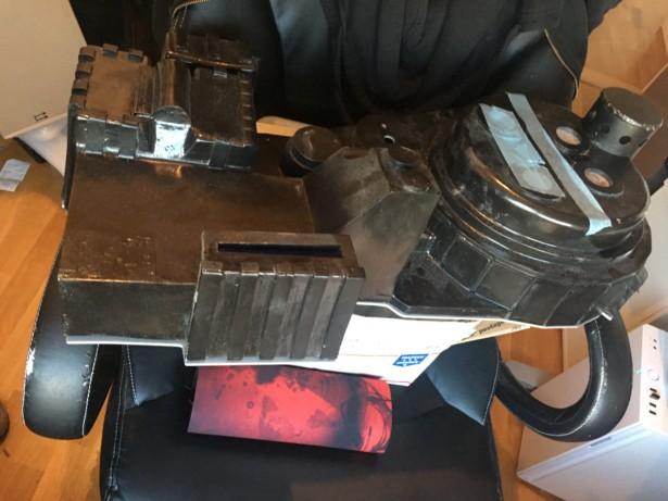
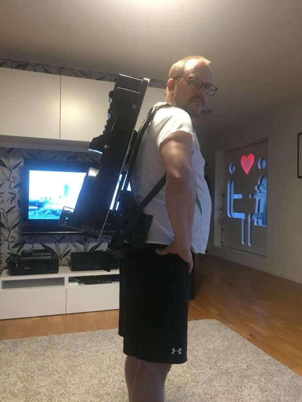
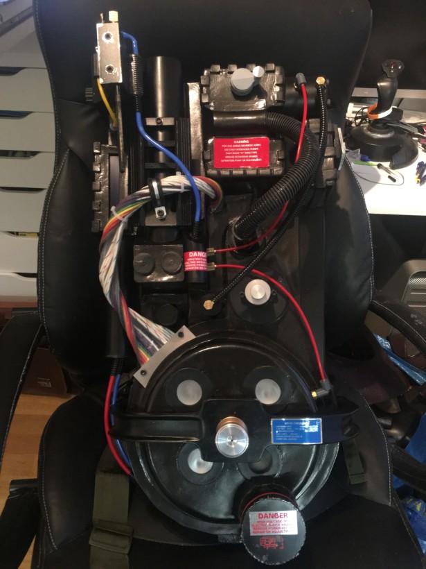
However: I decided that it was time to use the resin parts I had laying about and start putting the pack together!

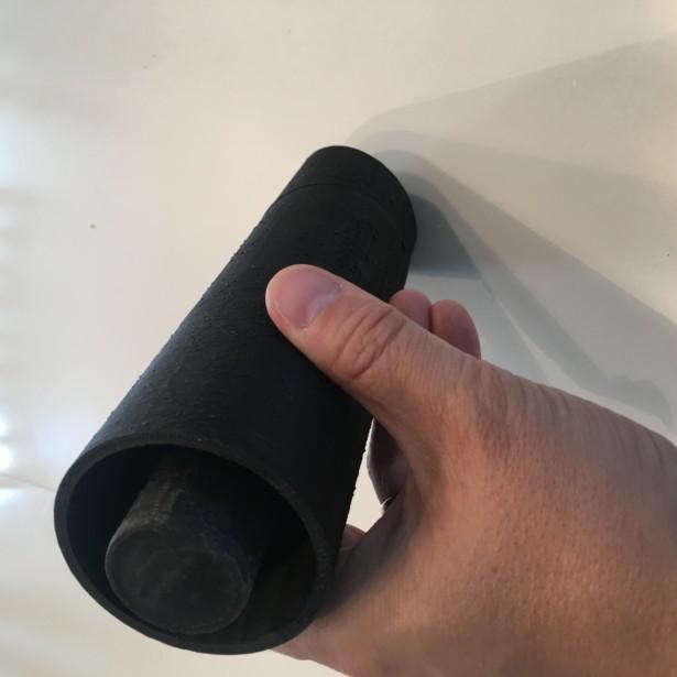
One of the first things I assembled was the Ion arm:

Image

This was the easy part, but as the ion arm made from resin is hollow, and basically has no base plate, I had no idea how to mount it yet, as I want to be able to one day replace the resin parts with metal, as the original plane was. While I was thinking about it, I started drilling and fastening and putting some other parts together.
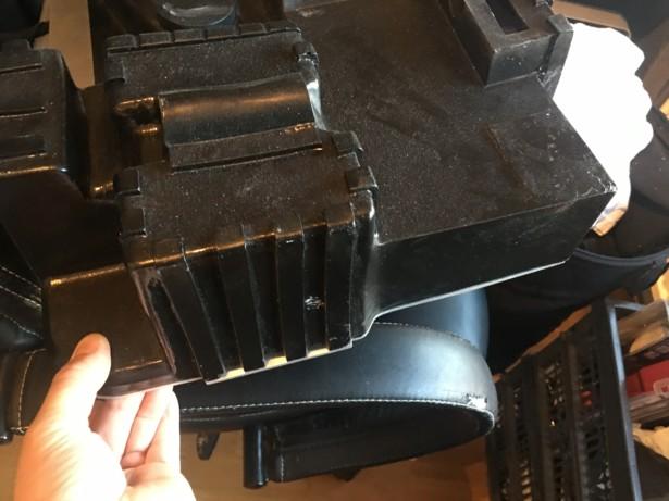
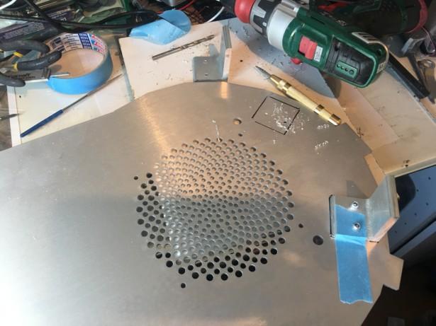
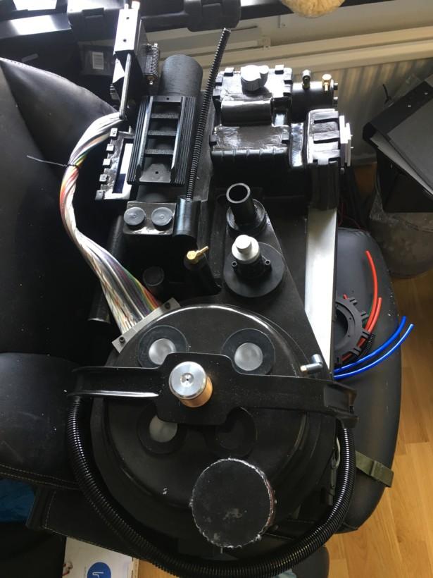
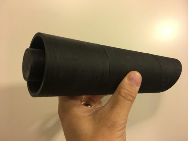
Next up, the HGA:

Image

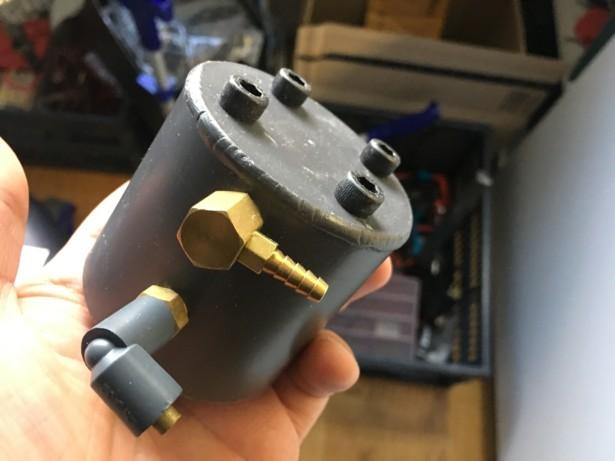
I then simply drilled and fastened the beam line, and filler tubes, the injector tubes and the vacuum tube. All these were done by printing out the mount plate I designed for the metal parts to paper, tape one copy to the resin part to get the hole configuration, and one copy to the pack to drill the holes where they should be!

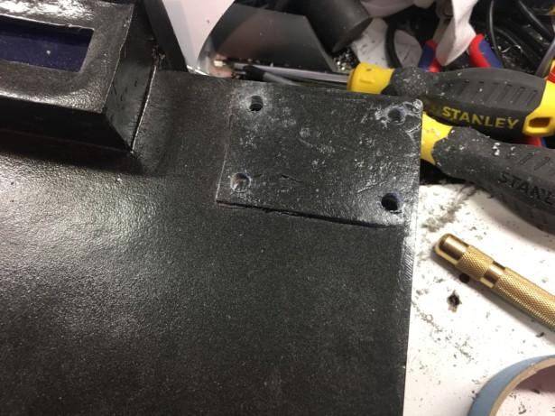
Measure twice and drill once... At least that's what I should have done. When I started adding things like the bumper, I realised after a while that it was a bit crooked.

Image

Not a big issue, I plugged the hole with some epoxy putty and measured (the second time), correct this time, and drilled a new hole.

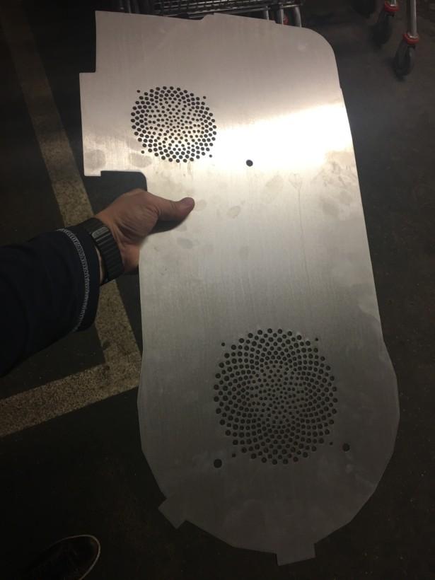
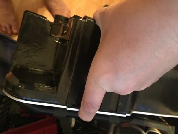
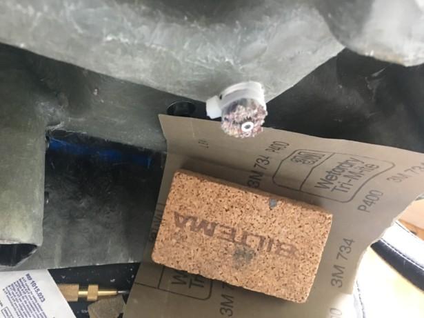
For the bracket that holds the injector tubes, I used this:

Image

I cut it down to size, and used a file to round off the edges...

Image

Then simply put a large clamp on it, and used my body weight to bend it to 90 degrees against a piece of wood. Then drill holes and screw it in to place in both the injector tubes and the shell. I decided to use screws since I want to be able to replace these at some point...

Image

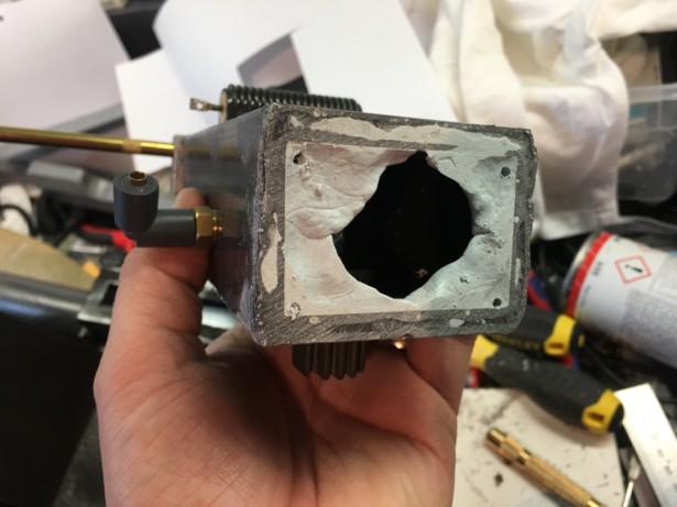
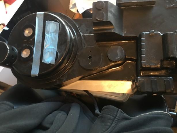
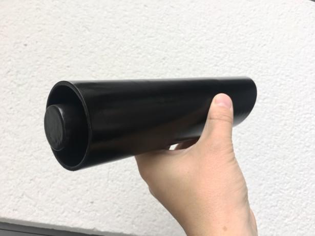
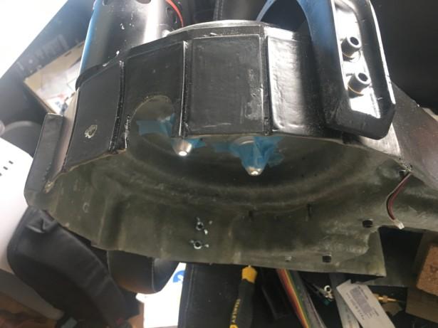
To fasten the HGA, I taped a piece of paper around the round, open edge, and used a scalpel to cut around the inside edge to get the inner circumference, and cut a scrap piece of 3mm styrene I had laying about to the same size. I then pressed some epoxy putty around the inner edge of the tube and pressed the styrene circle inside and let it sit until the epoxy had hardened. Once cured, I simply used the paper pattern from my virtual HGA in order to get the holes where I wanted them to be. I then tapped the holes and everything was done!

Image

The Ion arm I tried something different. Since I only really needed to make holes near the corners, I built up the inside of the hollow ion arm with two-component epoxy putty. Same stuff I used on the HGA. Once it was almost cured, I sanded off the chunks and carefully drilled some pilot holes.

Image

Once fully cured, I tapped these as well and I drilled the corresponding holes in the shell.

Image

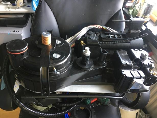
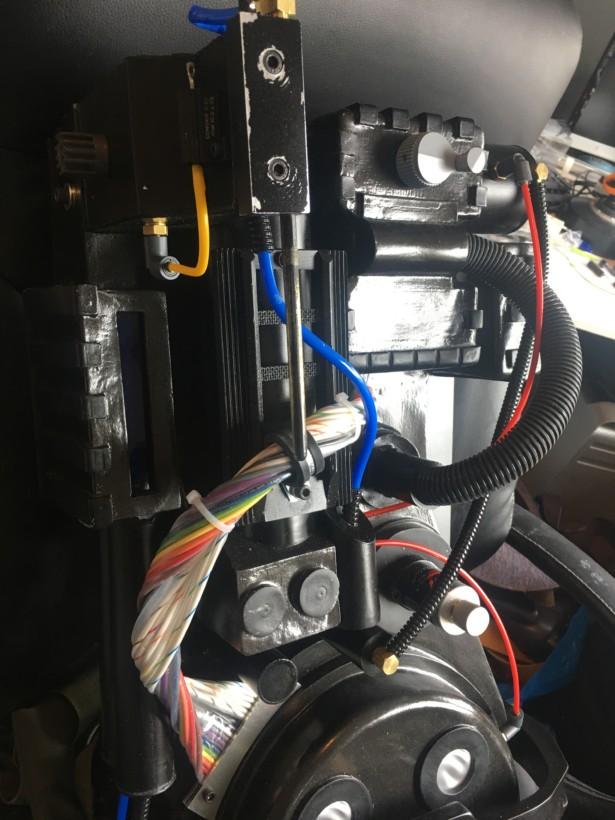
Last step for tonight, was to drill and tap the holes for the cable clamp. Naturally I had to add the cable just for fun. I also drilled the hole in the shell where the cable will end up, eventually. The cable needs to be quite a bit shorter, but as I haven't made my booster tube yet, I won't cut it just yet.

Image

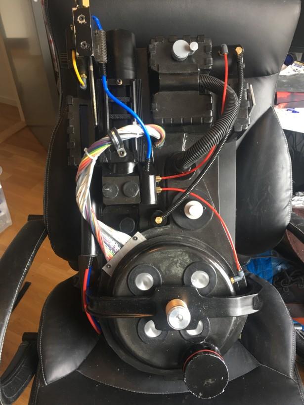
I am fast reaching the end of the things that can be done on the outside of the pack, apart from painting the resin parts. I've got a few more holes to drill and places for cables to run, and making that booster tube, but other than that, things start to look pretty good.

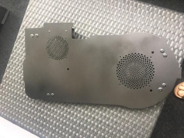
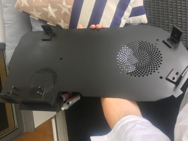
I do however still have a lot to do on the thrower, where I plan to 3d print panels for the inside of the thrower, to hold the electronics and rumble pack in place, and use the existing bolts from the outside to mount these panels. Hopefully, it will work!

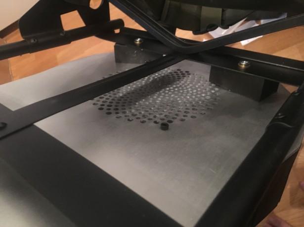
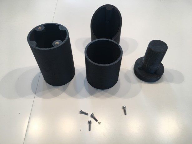
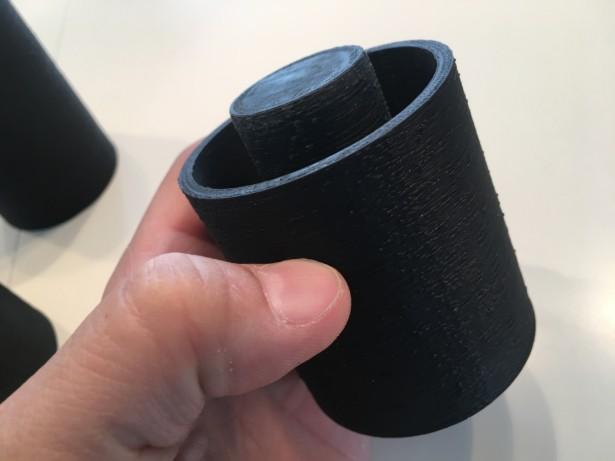
One thing I have started on designing, is a holder for the reflectors for the cyclotron that are pushed against the lenses with springs, in order to have them as close as possible.

The reasoning behind this, is that I really don't want anything at all connected to the shell, so I can simply lift it off and have everything sitting on the motherboard.

I've printed out a few smaller pieces to test sizes, but I have yet to print out a POC, but I am aiming for something like this to hold my reflectors...

Image
More to come soon...
twmedford23 liked this
#4894430
One of the few items I have left on my pack is the booster tube.
I sourced a few nearby stores for fitting tubes in PVC, but found none that were even near the proper diameter, so I decided to make my own. Let's get that 3D printer to work!

Image

Now, this print went over night and when I started it last night, I was tired and used the wrong settings, so it is all spotty and blobby, but that is fixed in the upcoming version I am printing with proper settings.

Here are all the parts:

Image

The booster plug just fits inside the outermost part of the booster tube, and is fastened from the inside with an m3 bolt.

Image

Image

All parts of the tube are designed to be screwed together to help when gluing them. I use these brass inserts that I just head press into the plastic and i just love them!

Image

They are simply pressed into the plastic with my soldering iron, so they are melted in place.

Image

Image

All three parts fit together, and all holes are already made into the design.

Image

Apart from the annoying spots, this looks pretty ok!

Image

Image

Here is the new booster tube, printing as I write this, and will keep on printing for another 10 hours or so. It looks much better when printed with the correct settings!

Image

Finally a few shots of the pack with all now painted and fastened parts, apart from the booster tube and frame, which are the last parts to be mounted on the pack.

Image

Image
twmedford23 liked this
#4894487
To continue where I left off yesterday, I continued the work on the Booster on my Ghostbusters Proton pack.

I took the raw 3d print, sanded off the biggest irregularities and then covered it heavily in spray filler. Once cured, it was time to sand it off again...

Image

Two rounds of spray filler and sanding off until it was smooth, then time to start painting. The key to paint with spray colours is to build it up in thin layers and let them dry in between.

Image

Once the paint was dry enough (it also dries a LOT faster when you apply it in small layers), it was time to clear coat the booster.

Image

Once dry, it was time to mount on the proton pack. The mounting was done fairly easily and quickly. In reality, I should do a weld line around the booster, but as I am planning to replace this (possibly) with an aluminium tube at some point, I have opted to not do this just yet. We'll see. If so I have the weld line to build up with epoxy resin, and also to do the "ugly weld" between the booster and the Ion arm.

Image

Image

So far, so good.

One of my pet peeves when it comes to 3d printing is that many people unfortunately do not put in the effort of making their prints smooth. Some people wishes to keep the 3d print lines as a statement, which is fine, but many prop makers don't use the tool to its full potential: which in my world means to use the 3d printer to save time when building the core item, and the time saved in construction can be put into finishing instead. If used like this, and you use smart methods when doing the finish, you will save time overall and still have a prop that looks great!

Last piece to do on the outside of the pack: paint the motherboard, do the ugly weld and (possibly) the weld around the booster tube, then time for the dressing of the pack, adding labels, routing all the little cables and stuff that makes it look great.

There is still a LOT to be done on the inside of the pack, not to mention the thrower that I've barely started with. My plan for the thrower is to 3d print mounting panels to be placed on the inside of the thrower to hold the electronics in place.
#4894557
Over the weekend, I've managed to get quite a lot done.
Building is an outlet for me. It is a perfect way to relieve stress and think of other things, so particularly after an intense week with lots of ups and downs, like this one has been, really diving head first in to building is the best way to clear my head!

One of the things I don't like as much, is painting. I don't have a proper place to paint, and I'm not very good at spray cans, but still, I make do with what I have.

First off, it was time to spray the motherboard to get rid of that raw metal feel.

As always, a few thin layers is key here...

Image

.. to build up more thin fast drying layers, until it is all covered and the clear coat goes on.

Image

I've painted both the inside and outside of my motherboard, I figured it would be the neatest way, really.

Next up, I spent more time attaching things to the shell itself, like this painted v-hook to hang the thrower on. I cut off the bolts with a hand saw and sanded them flush by hand.

Image

Some of the things that are screwed on from the outside, I've made it easier to remove, if needed. For the shock mount, I used wing nuts. It is also a good way to stop this from being overly tight and damaging the resin.

Image

In the picture you also clearly see the mouse-hole cut out for the loom holder I made a while back. This holder will be superglued to the motherboard for now. It seems to be holding up very well so far.

I also adjusted the length of the cable, and finally took the decision to cut it off with my hand saw. I screwed in a bolt from the inside to press against the cable tiles and make it even sturdier, but this baby is not going anywhere.

Image

I used the same idea on my copper foot wires on my R2-D2, where I used a rubber hose inside it, and had a screw inside a plug that forced it shut.

Since I started running out of things to do on the basic pack for now, I started dressing the pack. A few cables here...

Image

... and a few cables there...

Image

... and some more over here...

Image

... and don't forget around the Ion arm ...

Image

... and things are starting to look good.

As the more observant of you may have realized, I've flipped my ribbon cable. Some screen shot references from Ghostbuster (the Original movie from 1984) revealed that some of these ribbon cables were mounted just like mine was first, but on some packs, it was not orientated in the same way. That's the beauty of prop building. Finding these little irregularities.

As I've modeled mine after the "Spengler" pack, ie the pack that was used by the late Harold Ramis as Egon Spengler in the movie, I twisted mine another half lap to get the rainbow coloured cables facing the outside of the pack. One of these details only a true nerd would ever see.

Here's finally the pack in all its glory.

Image

.. and here it is with some labels I had laying about attached at random places.

Image

Of course there are still things to do on the pack itself. Normally there is an ugly weld between the Ion arm and the Booster tube, and the Booster tube should be welded on to the pack. Mine is just pressed against it for now. I may or may not fix this, depending on what look I want to go for. It is not a difficult thing to add, it all just depends on if I want to replace the resin parts with metal parts in the future or not.

Another thing that is still on the "to do" list is weathering. Once the entire pack (with thrower) is complete, I will sit down in some sessions and do some proper weathering. It looks too brand new at this point.

Last but not least, electronics. I have still not done anything when it comes to electronics. There is also the nice power panel I made a while back that needs to be mounted, but the base pack is mostly done at this point, and that feels just great!

Next week, I'll start working on electronics and/or the thrower. Since the thrower has all the controls for the sounds and lights inside, it sort of can't be done one without the other.
Proton Props UK

That's strange, he gave me an entirely different r[…]

For anyone interested in seeing some of the orig[…]

Did anyone watch it?

We're bringing you the latest updates to the GBFan[…]